Subaru Impreza 3 / Impreza WRX / Impreza WRX STI. Service manual — part 228

EN(H4DOTC)(diag)-136
Diagnostic Procedure with Diagnostic Trouble Code (DTC)
ENGINE (DIAGNOSTICS)
Step
Check
Yes
No
1
CHECK CURRENT DATA.
1) Start the engine.
2) Read the value of «Intake Air Temp.» using
the Subaru Select Monitor or a general scan
tool.
NOTE:
• Subaru Select Monitor
For detailed operation procedures, refer to
“READ CURRENT DATA FOR ENGINE”. <Ref.
to EN(H4DOTC)(diag)-40, Subaru Select Moni-
tor.>
• General scan tool
For detailed operation procedures, refer to the
general scan tool operation manual.
Is the value of «Intake Air Temp.»
less than –40°C (–40°F)?
Even if DTC is
detected, the cir-
cuit has returned to
a normal condition
at this time. Repro-
duce the failure,
and then perform
the diagnosis
again.
NOTE:
In this case, tem-
porary poor con-
tact of connector,
temporary open or
short circuit of har-
ness may be the
cause.
2
CHECK FOR POOR CONTACT.
Check for poor contact of ECM and mass air
flow and intake air temperature sensor connec-
tor.
Is there poor contact of ECM or
mass air flow and intake air
temperature sensor connector?
Repair the poor
contact of ECM or
mass air flow and
intake air tempera-
ture sensor con-
nector.
3
CHECK HARNESS BETWEEN ECM AND
MASS AIR FLOW AND INTAKE AIR TEM-
PERATURE SENSOR CONNECTOR.
1) Turn the ignition switch to OFF.
2) Disconnect the connector from ECM and
the mass air flow and intake air temperature
sensor.
3) Measure the resistance of harness between
ECM connector and the mass air flow and
intake air temperature sensor connector.
Connector & terminal
(B136) No. 31 — (B3) No. 1:
(B135) No. 30 — (B3) No. 2:
Is the resistance less than 1 Ω? Go to step
Repair the harness
and connector.
NOTE:
In this case, repair
the following item:
• Open circuit in
harness between
ECM
connector
and the mass air
flow and intake air
temperature sen-
sor connector
• Poor contact of
joint connector
4
CHECK HARNESS BETWEEN ECM AND
MASS AIR FLOW AND INTAKE AIR TEM-
PERATURE SENSOR CONNECTOR.
1) Connect all connectors.
2) Turn the ignition switch to ON.
3) Measure the voltage between ECM connec-
tor and chassis ground.
Connector & terminal
(B136) No. 31 (+) — Chassis ground (–):
Is the voltage 5 V or more?
Repair the short
circuit of harness
to power supply
between ECM con-
nector and the
mass air flow and
intake air tempera-
ture sensor con-
nector.

EN(H4DOTC)(diag)-137
Diagnostic Procedure with Diagnostic Trouble Code (DTC)
ENGINE (DIAGNOSTICS)
W: DTC P0116 ENGINE COOLANT TEMPERATURE SENSOR 1 CIRCUIT
RANGE/PERFORMANCE
DTC DETECTING CONDITION:
• Detected when two consecutive driving cycles with fault occur.
• GENERAL DESCRIPTION <Ref. to GD(H4DOTC)-51, DTC P0116 ENGINE COOLANT TEMPERATURE
SENSOR 1 CIRCUIT RANGE/PERFORMANCE, Diagnostic Trouble Code (DTC) Detecting Criteria.>
TROUBLE SYMPTOM:
• Hard to start
• Improper idling
• Poor driving performance
CAUTION:
After servicing or replacing faulty parts, perform Clear Memory Mode <Ref. to EN(H4DOTC)(diag)-63,
OPERATION, Clear Memory Mode.>, and Inspection Mode <Ref. to EN(H4DOTC)(diag)-49, PROCE-
Step
Check
Yes
No
1
CHECK FOR ANY OTHER DTC ON DISPLAY. Is any other DTC displayed?
2
CHECK ENGINE COOLANT TEMPERATURE
SENSOR.
1) Disconnect the connectors from the engine
coolant temperature sensor.
2) Measure the resistance between engine
coolant temperature sensor terminals when the
engine coolant is cold and after warmed up.
Terminals
No. 1 — No. 2:
Is the resistance of engine cool-
ant temperature sensor differ-
ent between when engine
coolant is cold and after
warmed up?
Repair the poor
contact of ECM
connector.
EN(H4DOTC)(diag)-138
Diagnostic Procedure with Diagnostic Trouble Code (DTC)
ENGINE (DIAGNOSTICS)
X: DTC P0117 ENGINE COOLANT TEMPERATURE CIRCUIT LOW
DTC DETECTING CONDITION:
• Immediately at fault recognition
• GENERAL DESCRIPTION <Ref. to GD(H4DOTC)-53, DTC P0117 ENGINE COOLANT TEMPERATURE
CIRCUIT LOW, Diagnostic Trouble Code (DTC) Detecting Criteria.>
TROUBLE SYMPTOM:
• Hard to start
• Improper idling
• Poor driving performance
CAUTION:
After servicing or replacing faulty parts, perform Clear Memory Mode <Ref. to EN(H4DOTC)(diag)-63,
OPERATION, Clear Memory Mode.>, and Inspection Mode <Ref. to EN(H4DOTC)(diag)-49, PROCE-
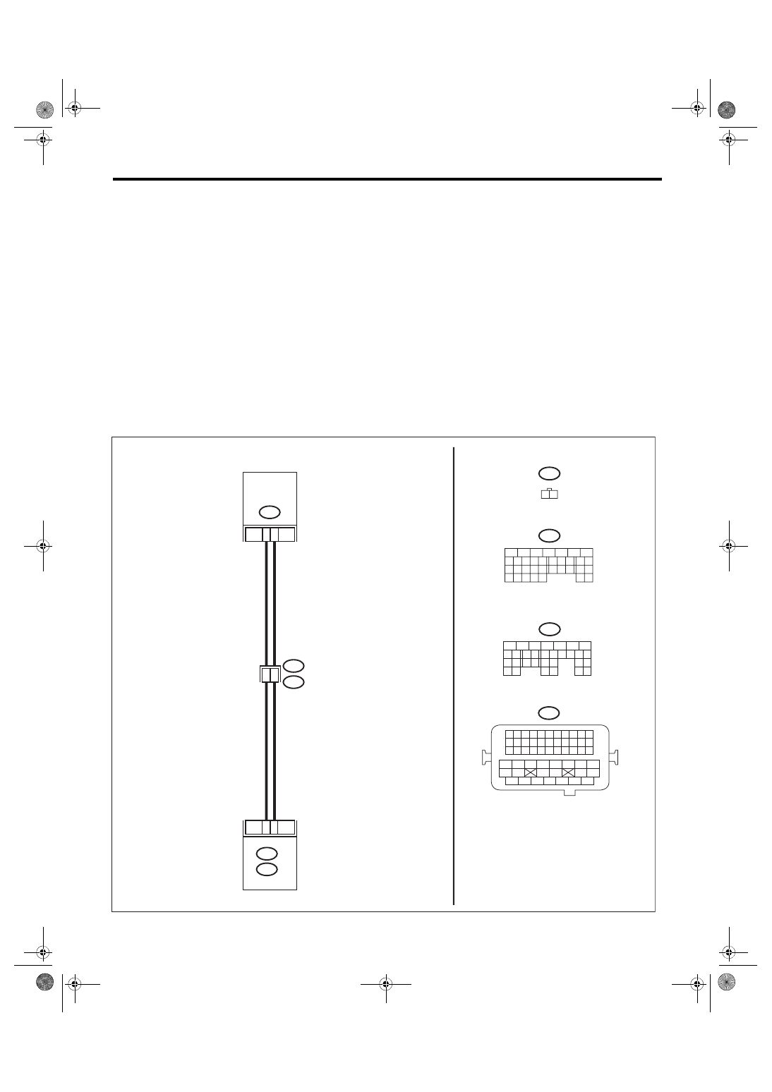
WIRING DIAGRAM:
• Engine electrical system, without SI-DRIVE <Ref. to WI-32, WITHOUT SI-DRIVE, WIRING DIAGRAM,
• Engine electrical system, with SI-DRIVE <Ref. to WI-48, WITH SI-DRIVE, WIRING DIAGRAM, Engine
ECM
EN-08726
B134
A:
B137
D:
D22
E8
2
1
12
6
E8
B134
B21
E2
A29
B137
D:
A:
31
30
29
28
27
21
20
19
18
17
16
26
25
24
15
14
13
12
11
23
22
10
3
4
9
1
2
8
7
6
5
31
30
32
29
34
33
21
20
19
18
17
16
28
27
26
15
14
13
12
11
25
23
22
24
10
3
4
9
1
2
8
7
6
5
2
1
54
52 53
50 51
48 49
46 47
45
44
42 43
40 41
38 39
36 37
34 35
33
32
31
30
29
28
27
26
25
24
23
22
21
20
11
10
9
19
18
17
16
8
7
6
5
15
14
13
12
4
3
2
1
B21
ENGINE
COOLANT
TEMPERATURE
SENSOR

EN(H4DOTC)(diag)-139
Diagnostic Procedure with Diagnostic Trouble Code (DTC)
ENGINE (DIAGNOSTICS)
Step
Check
Yes
No
1
CHECK CURRENT DATA.
1) Start the engine.
2) Read the value of «Coolant Temp.» using
the Subaru Select Monitor or a general scan
tool.
NOTE:
• Subaru Select Monitor
For detailed operation procedures, refer to
“READ CURRENT DATA FOR ENGINE”. <Ref.
to EN(H4DOTC)(diag)-40, Subaru Select Moni-
tor.>
• General scan tool
For detailed operation procedures, refer to the
general scan tool operation manual.
Is the value of «Coolant
Temp.» 150°C (302°F) or
more?
Even if DTC is
detected, the cir-
cuit has returned to
a normal condition
at this time. Repro-
duce the failure,
and then perform
the diagnosis
again.
NOTE:
In this case, tem-
porary poor con-
tact of connector,
temporary open or
short circuit of har-
ness may be the
cause.
2
CHECK HARNESS BETWEEN ECM AND EN-
GINE COOLANT TEMPERATURE SENSOR
CONNECTOR.
1) Turn the ignition switch to OFF.
2) Disconnect the connectors from ECM and
engine coolant temperature sensor.
3) Measure the resistance between ECM con-
nector and chassis ground.
Connector & terminal
(B137) No. 22 — Chassis ground:
Is the resistance 1 MΩ or
more?
Repair the short
circuit to ground in
harness between
ECM connector
and engine coolant
temperature sen-
sor connector.
Нет комментариевНе стесняйтесь поделиться с нами вашим ценным мнением.
Текст