Subaru Impreza 3 / Impreza WRX / Impreza WRX STI. Service manual — part 659
OD(diag)-9
General Description
OCCUPANT DETECTION SYSTEM (DIAGNOSTICS)
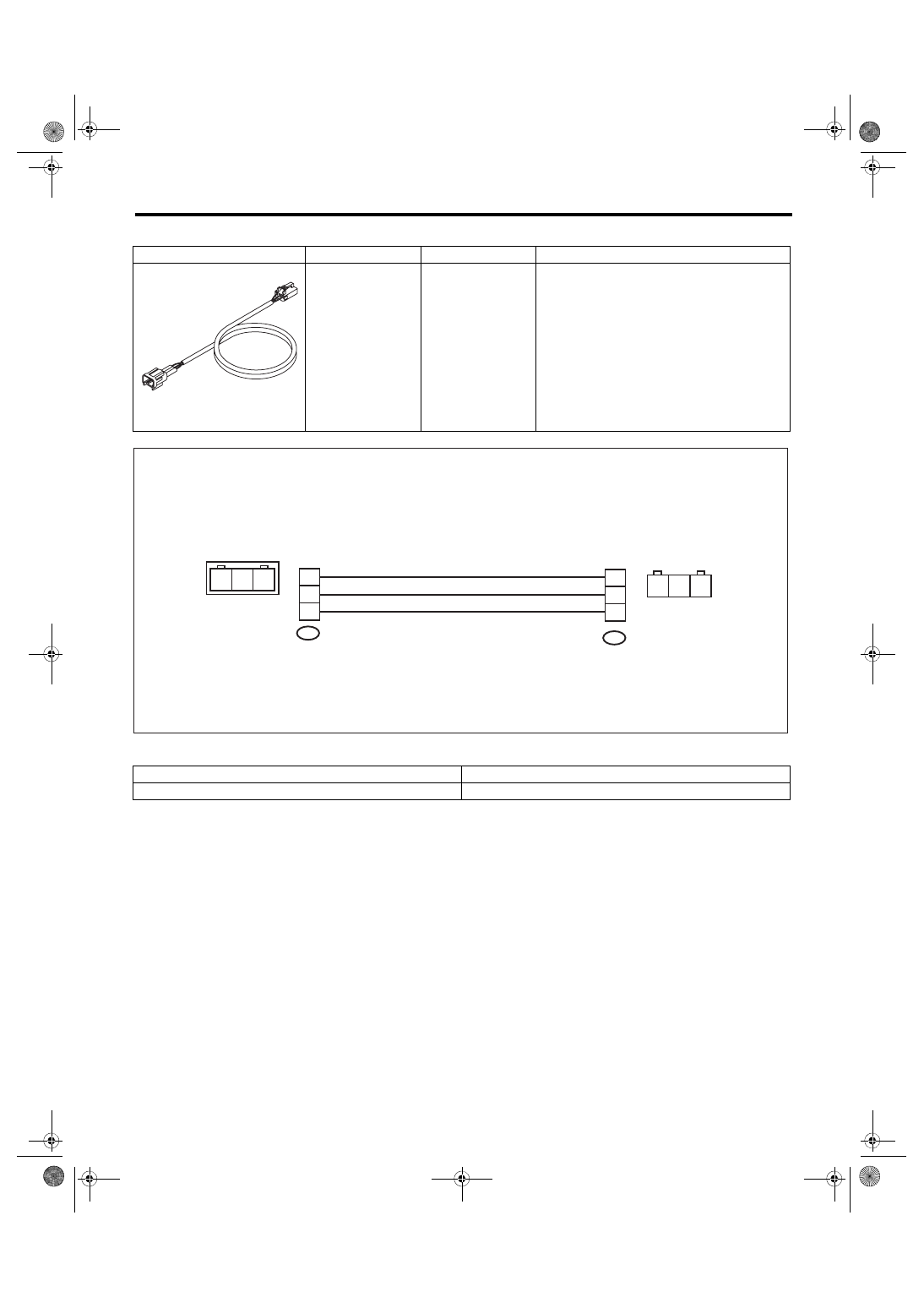
• TEST HARNESS AD
2. GENERAL TOOL
ILLUSTRATION
TOOL NUMBER
DESCRIPTION
REMARKS
98299XA020
TEST HARNESS
AD
Used when measuring voltage and resistance of
the seat belt tension sensor.
TOOL NAME
REMARKS
Circuit tester
Used for measuring resistance, voltage and current.
ST98299XA020
OD-00028
1AD
2AD
3
2
1
3
1
2
3
2
1
3
1
2
OD(diag)-10
Electrical Component Location
OCCUPANT DETECTION SYSTEM (DIAGNOSTICS)
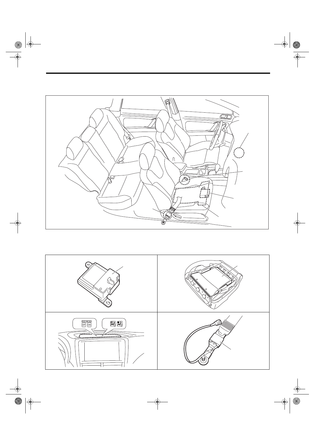
4. Electrical Component Location
A: LOCATION
(1)
Occupant detection control mod-
ule
(3)
Airbag ON/OFF indicator light
(5)
Seat belt tension sensor
(2)
Occupant detection sensor
(4)
Buckle switch (passenger’s seat)
(4)
(3)
OD-00076
(2)
(5)
(1)
OD-00016
(1)
OD-00015
(2)
OD-00098
(3)
(3)
OD-00017
(5)
OD(diag)-11
Airbag Connector
OCCUPANT DETECTION SYSTEM (DIAGNOSTICS)
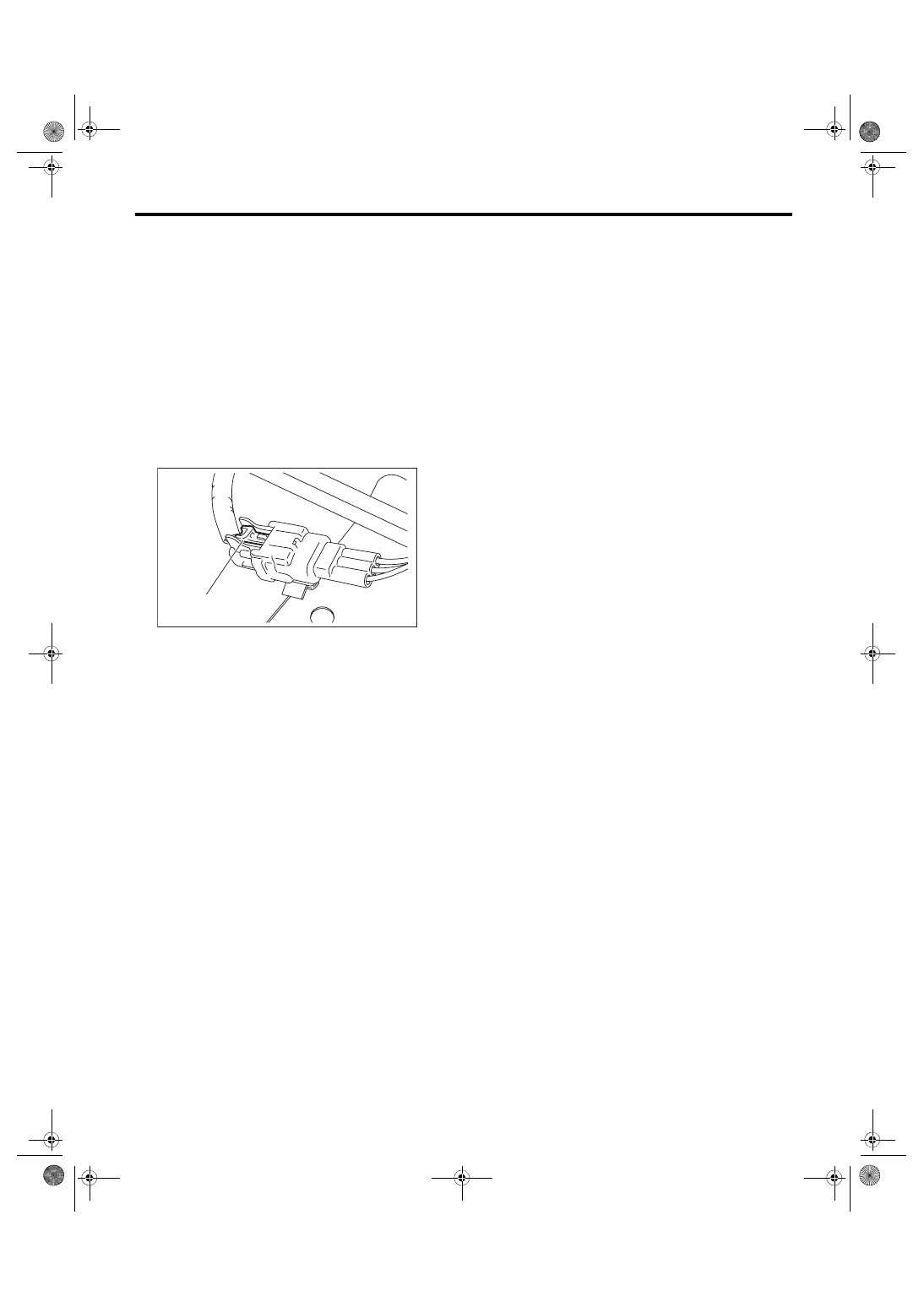
5. Airbag Connector
A: PROCEDURE
1. OCCUPANT DETECTION SYSTEM (BE-
TWEEN AIRBAG REAR HARNESS AND
SEAT HARNESS) AND BELT TENSION
SENSOR
1) How to disconnect:
Press the lock arm (A) and disconnect the connec-
tor.
CAUTION:
When pulling the slide lock or disconnecting
connector, be sure to hold the connector, not
the harness.
2) How to connect:
Holding the connector, push it in securely until a
clicking sound is heard.
CAUTION:
Be sure to insert the connector in until it is
locked. Then pull it gently to make sure that it is
locked.
2. AIRBAG CONTROL MODULE
Refer to the airbag system section. <Ref. to AB-8,
AIRBAG CONTROL MODULE, PROCEDURE, Air-
3. BUCKLE SWITCH RH
Refer to the airbag system section. <Ref. to AB-11,
BUCKLE SWITCH RH, PROCEDURE, Airbag
AB-01325
(A)
OD(diag)-12
Control Module I/O Signal
OCCUPANT DETECTION SYSTEM (DIAGNOSTICS)
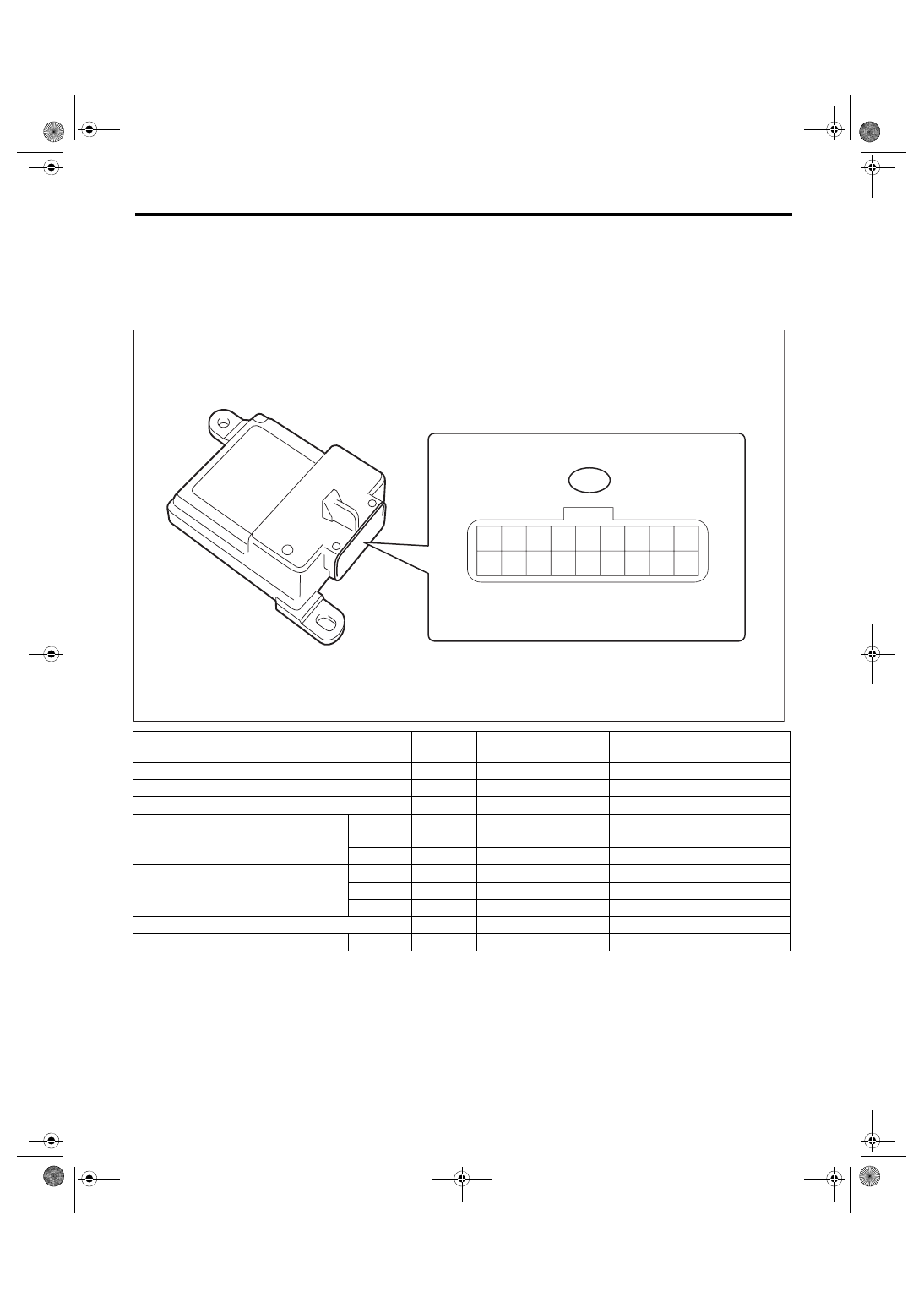
6. Control Module I/O Signal
A: ELECTRICAL SPECIFICATION
CAUTION:
Never remove the occupant detection control module, occupant detection sensor or seat frame be-
cause they are integrated into one unit.
B: WIRING DIAGRAM
Refer to the electrical wiring diagram. <Ref. to WI-87, WIRING DIAGRAM, Occupant Detection System.>
Terminal name
Terminal
No.
Input/Output value
Remarks
IG – power supply
9
9 — 16 V
When ignition switch ON
Airbag control module communication
(COM)
10
Open collector terminal
Communication line
Airbag control module communication
(GND)
5
0 V
Ground
Belt tension sensor
(Vcc)
4
0 — 5 V
Belt tension sensor power supply
(Vout)
16
0.5 — 4.5 V
Sensor output voltage
(GND)
14
0 V
Sensor ground
Occupant detection sensor
(Vcc)
6
0 — 5 V
Pressure sensor power supply
(Vout)
7
0.5 — 4.5 V
Sensor output voltage
(GND)
15
0 V
Sensor ground
Buckle switch
1
0 — IG voltage
Ignition voltage when switch ON
Buckle switch
(GND)
2
0 V
Switch ground
AB61
1
2
3
4
5
6
7
8
9
11
12
13
14
15
16
17
18
10
OD-00099
TO
Нет комментариевНе стесняйтесь поделиться с нами вашим ценным мнением.
Текст