Subaru Impreza 3 / Impreza WRX / Impreza WRX STI. Service manual — part 593
AC-31
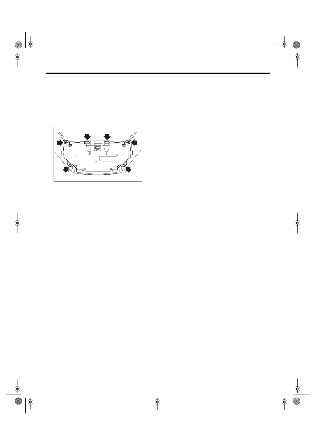
Control Unit (Auto A/C Model)
HVAC SYSTEM (HEATER, VENTILATOR AND A/C)
14.Control Unit (Auto A/C Model)
A: REMOVAL
1) Disconnect the ground cable from battery.
2) Remove the ornament panel. <Ref. to EI-52,
ORNAMENT PANEL, REMOVAL, Center Con-
3) Remove the screws and claws, and remove the
control module from the ornament panel.
B: INSTALLATION
Install each part in the reverse order of removal.
Tightening torque:
Refer to “COMPONENT” of “General Descrip-
tion”. <Ref. to AC-7, CONTROL MODULE,
COMPONENT, General Description.>
AC-01738
AC-32
Compressor
HVAC SYSTEM (HEATER, VENTILATOR AND A/C)
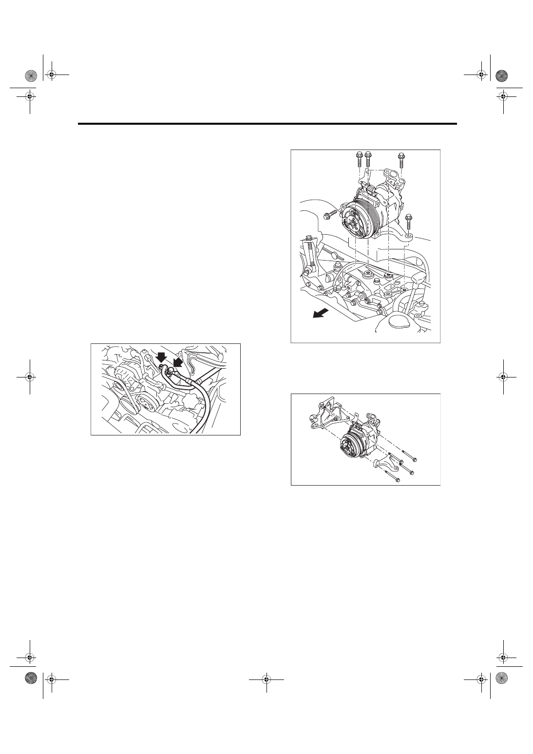
15.Compressor
A: REMOVAL
1) Perform compressor oil return operation. <Ref.
to AC-24, PROCEDURE, Compressor Oil.>
2) Turn the A/C switch to OFF and stop the engine.
3) Using the refrigerant recovery system, dis-
charge refrigerant. <Ref. to AC-19, PROCEDURE,
Refrigerant Recovery Procedure.>
4) Disconnect the ground cable from battery.
5) Remove the V-belts.
• Except for STI model: <Ref. to ME(w/o STI)-38,
• STI model: <Ref. to ME(STI)-40, REMOVAL, V-
6) Remove the generator. <Ref. to SC(STI)-21,
7) Remove the bolt and remove the low-pressure
hose and high-pressure hose.
CAUTION:
Seal the disconnected hose and engaging part
of compressor with a plug or vinyl tape to pre-
vent foreign matter from entering.
8) Disconnect the compressor connector.
9) Remove the bolts and remove the compressor
bracket.
NOTE:
Since the compressor cannot be removed by itself,
remove the compressor bracket as a unit.
10) Remove the bolts, then remove the bracket
from the compressor.
AC-01739
AC-01740
AC-01741
AC-33
Compressor
HVAC SYSTEM (HEATER, VENTILATOR AND A/C)
B: INSTALLATION
CAUTION:
• Replace the O-rings on hoses or pipes with
new parts, and then apply compressor oil.
• After replacing the compressor, adjust the
amount of the compressor oil. <Ref. to AC-24,
1) Install each part in the reverse order of removal.
2) Charge refrigerant. <Ref. to AC-20, PROCE-
DURE, Refrigerant Charging Procedure.>
Tightening torque:
Refer to “COMPONENT” of “General Descrip-
tion”.
• Air conditioning unit: <Ref. to AC-9, AIR
CONDITIONING UNIT, COMPONENT, General
• Compressor: <Ref. to AC-10, COMPRESSOR,
COMPONENT, General Description.>
C: INSPECTION
1. MAGNETIC CLUTCH CLEARANCE
1) Check the clearance of entire circumference
around the drive plate and pulley.
Specification:
0.3 — 0.6 mm (0.0118 — 0.0236 in)
2) Replace the compressor if the inspection result
is not within the standard value.
2. MAGNETIC CLUTCH OPERATION
1) Disconnect the compressor connector.
2) Connect the battery positive (+) terminal to the
terminal of the compressor connector and check
the magnet clutch engagement.
3) If the magnet clutch does not operate normally,
replace the compressor.
AC-34
Condenser
HVAC SYSTEM (HEATER, VENTILATOR AND A/C)
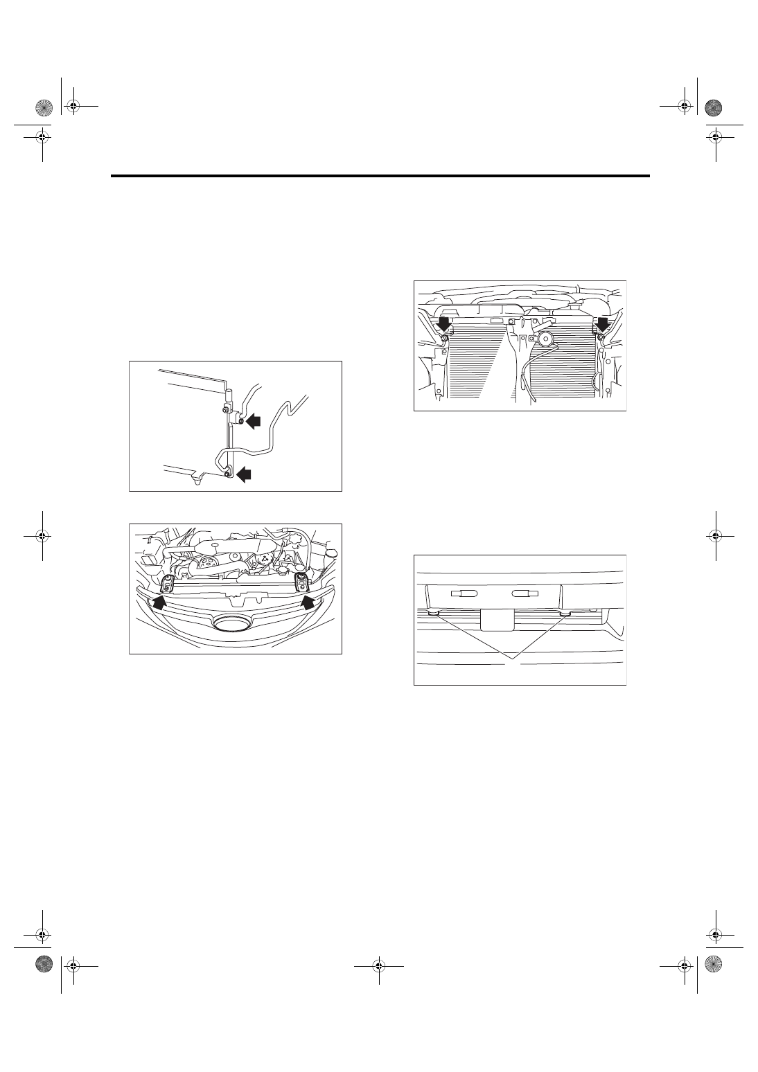
16.Condenser
A: REMOVAL
1) Using the refrigerant recovery system, dis-
charge refrigerant. <Ref. to AC-19, PROCEDURE,
Refrigerant Recovery Procedure.>
2) Disconnect the ground cable from battery.
3) Disconnect the high pressure hose and pipe
from the condenser.
CAUTION:
Seal the disconnected hose, pipe and engaging
part of condenser assembly with a plug or vinyl
tape to prevent foreign matter from entering.
4) Remove the bolts and remove the radiator upper
bracket.
5) Remove the front bumper face. <Ref. to EI-31,
FRONT BUMPER FACE, REMOVAL, Front
6) Remove the bolts, and lift the condenser to pull it
out through space between the radiator and the ra-
diator panel.
CAUTION:
Be careful not to damage the condenser fins. If
a damaged fin is found, repair it using a thin
screwdriver.
B: INSTALLATION
CAUTION:
• Replace the O-rings on hoses or pipes with
new parts, and then apply compressor oil.
• If the condenser has been replaced, add an
appropriate amount of compressor oil to the
compressor. <Ref. to AC-24, ADJUSTMENT,
• Confirm that lower guide (A) of condenser
fits into holes on radiator panel.
1) Install each part in the reverse order of removal.
2) Charge refrigerant. <Ref. to AC-20, PROCE-
DURE, Refrigerant Charging Procedure.>
Tightening torque:
Refer to “COMPONENT” of “General Descrip-
tion”.
• Air conditioning unit: <Ref. to AC-9, AIR
CONDITIONING UNIT, COMPONENT, General
• Radiator & radiator fan: <Ref. to CO(STI)-4,
RADIATOR AND RADIATOR FAN, COMPO-
3) Adjust the fog light beam. (Model with fog light)
<Ref. to LI-21, FOG LIGHT AIMING, ADJUST-
MENT, Front Fog Light Assembly.>
AC-01793
AC-01742
AC-01743
AC-00631
(A)
Нет комментариевНе стесняйтесь поделиться с нами вашим ценным мнением.
Текст