Subaru Impreza 3 / Impreza WRX / Impreza WRX STI. Service manual — part 207
EN(H4DOTC)(diag)-52
Inspection Mode
ENGINE (DIAGNOSTICS)
1. PREPARATION FOR THE INSPECTION
MODE
1) Check that the battery voltage is 12 V or more
and fuel remains approx. half [20 — 40 L (5.3 —
10.6 US gal, 4.4 — 8.8 Imp gal)].
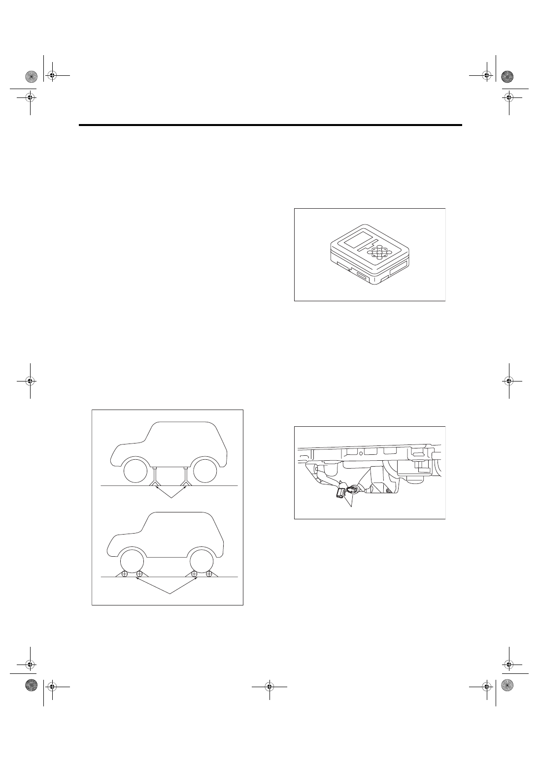
2) Lift up the vehicle using a garage jack and place
it on rigid racks, or drive the vehicle onto free roll-
ers.
WARNING:
• Before lifting up the vehicle, ensure parking
brake is applied.
• Do not use a pantograph jack in place of a rig-
id rack.
• Secure a rope or wire to the front or rear tow-
ing hooks to prevent the lateral runout of front
wheels.
• Before rotating the wheels, make sure that
there is no one in front of the vehicle. Besides
while the wheels are rotating, make sure that no
one approaches the vehicle front side.
• Make sure that there is nothing around the
wheels. For AWD model, pay attention to all
four wheels.
• While servicing, do not depress or release
the clutch pedal or accelerator pedal quickly re-
gardless of the engine speed. Quick operation
may cause the vehicle to drop off the free roller.
• To prevent the vehicle from slipping due to
vibration, do not place anything between rigid
rack and the vehicle.
2. SUBARU SELECT MONITOR
1) Check that no DTC remains after clearing mem-
ory. <Ref. to EN(H4DOTC)(diag)-63, Clear Memo-
2) Warm up the engine.
3) Prepare the Subaru Select Monitor kit. <Ref. to
EN(H4DOTC)(diag)-8, PREPARATION TOOL,
4) Prepare PC with Subaru Select Monitor in-
stalled.
5) Connect the USB cable to SDI (Subaru Diagno-
sis Interface) and USB port on the personal com-
puter (dedicated port for the Subaru Select
Monitor).
NOTE:
The dedicated port for the Subaru Select Monitor
means the USB port which was used to install the
Subaru Select Monitor.
6) Connect the diagnosis cable to SDI.
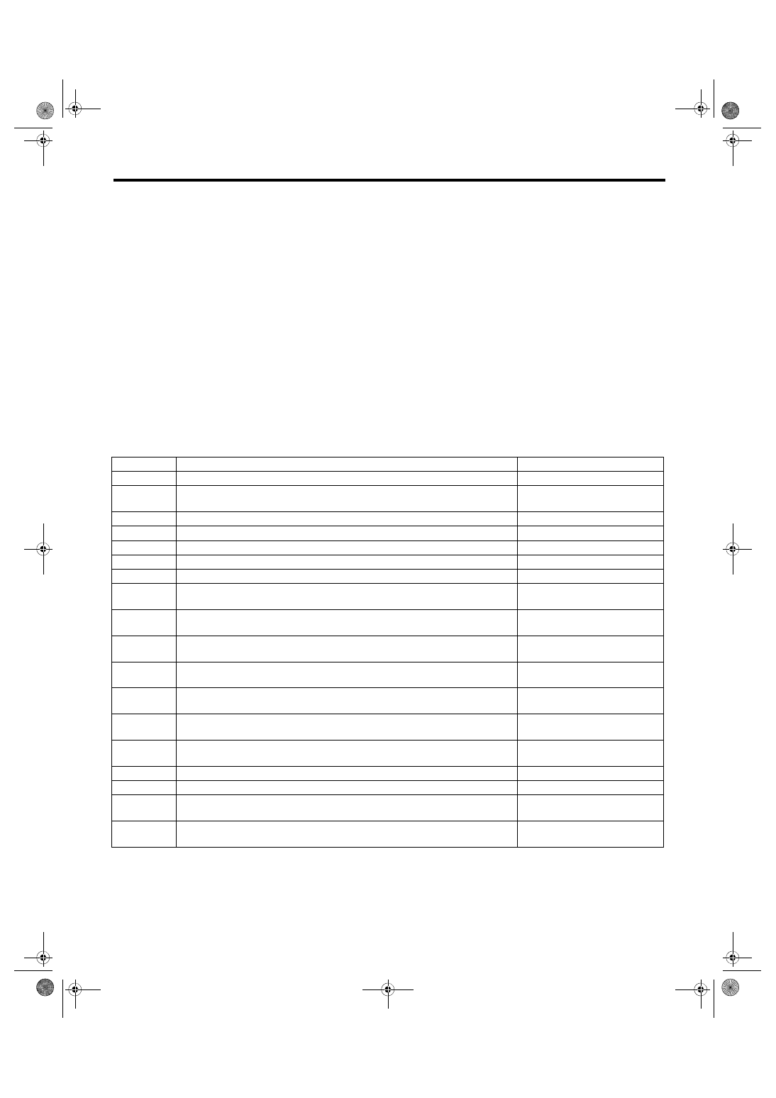
7) Connect the delivery (test) mode connector (A)
located under the glove box.
(A) Rigid rack
(B) Free roller
EN-00041
(A)
(B)
EN-05692
EN-06146
(A)

EN(H4DOTC)(diag)-53
Inspection Mode
ENGINE (DIAGNOSTICS)
8) Connect SDI to data link connector located in the
lower portion of the instrument panel (on the driv-
er’s side).
CAUTION:
Do not connect the scan tools except for Suba-
ru Select Monitor and general scan tool.
9) Start the PC.
10) Turn the ignition switch to ON (engine OFF)
and run the “PC application for Subaru Select Mon-
itor”.
11) On «Main Menu» display, select {Each System
Check}.
12) On «System Selection Menu» display, select
{Engine Control System}.
13) Click the [OK] button after the information of
engine type has been displayed.
14) On «Engine Diagnosis» display, select {Dealer
Check Mode Procedure}.
15) When the “Perform Inspection (Dealer Check)
Mode ?” is shown on the screen, click the [Next]
button.
16) Perform subsequent procedures as instructed
on the display screen.
• If trouble still remains in the memory, the corre-
sponding DTC appears on the display screen.
NOTE:
• For detailed operation procedures, refer to
“PC application help for Subaru Select Monitor”.
• For details concerning DTC, refer to “List of Di-
agnostic Trouble Code (DTC)”.
<Ref. to EN(H4DOTC)(diag)-87, List of Diagnos-
• Release the parking brake.
• The rotating speed difference between front
and rear wheels may illuminate the ABS warning
light, but this does not indicate a malfunction.
When engine control system diagnosis is fin-
ished, perform the VDC memory clearance pro-
cedure of self-diagnosis function. <Ref. to
VDC(diag)-27, Clear Memory Mode.>
3. GENERAL SCAN TOOL
1) Check that no DTC remains after clearing mem-
ory. <Ref. to EN(H4DOTC)(diag)-63, Clear Memo-
2) Warm up the engine.
3) Connect the delivery (test) mode connector (A)
located under the glove box.
4) Connect the general scan tool to data link con-
nector located in the lower portion of the instrument
panel (on the driver’s side).
CAUTION:
Do not connect the scan tools except for Suba-
ru Select Monitor and general scan tool.
5) Start the engine.
NOTE:
Depress the clutch pedal when starting engine.
6) Turn the neutral position switch to ON by operat-
ing shift lever.
7) Keep the engine speed in 2,500 — 3,000 rpm
range for 40 seconds.
EN-06148
EN-06146
(A)
EN-06148
EN(H4DOTC)(diag)-54
Inspection Mode
ENGINE (DIAGNOSTICS)
8) Place the shift lever in 1st gear and drive the ve-
hicle at 5 to 10 km/h (3 to 6 MPH).
NOTE:
• For AWD model, release the parking brake.
• The rotating speed difference between front and
rear wheels may illuminate the ABS warning light,
but this does not indicate a malfunction. When en-
gine control system diagnosis is finished, perform
the VDC memory clearance procedure of self-diag-
nosis function. <Ref. to VDC(diag)-27, Clear Mem-
9) Using the general scan tool, check for DTC and
record the result(s).
NOTE:
• For detailed operation procedures, refer to the
general scan tool operation manual.
• For details concerning DTC, refer to “List of Diag-
nostic Trouble Code (DTC)”.
EN(H4DOTC)(diag)-55
Drive Cycle
ENGINE (DIAGNOSTICS)
12.Drive Cycle
A: PROCEDURE
It is necessary to perform the drive cycle listed below if DTC is not found in the Inspection Mode. It is possible
to complete diagnosis of the DTC by performing the indicated drive cycle. After the repair for the DTC, per-
form a necessary drive cycle and make sure the function recovers and the DTC is recorded.
1. PREPARATION FOR DRIVE CYCLE
1) Check that the battery voltage is 12 V or more and fuel remains approx. half [20 — 40 L (5.3 — 10.6 US gal,
4.4 — 8.8 Imp gal)].
2) After performing the diagnostics and Clear Memory Mode, check that no DTC remains. <Ref. to
EN(H4DOTC)(diag)-63, Clear Memory Mode.>
3) Check the delivery (test) mode connector is disconnected.
NOTE:
• Perform the drive cycle after warming up the engine except when the engine coolant temperature at en-
gine start is specified.
• Perform the drive cycle twice if the DTC in the list is marked with *. After completing the first drive cycle,
stop the engine and perform second diagnosis in same condition.
2. DRIVE CYCLE A
Diagnostic procedure:
1) Drive for 20 minutes or more at a constant speed of 80 km/h (50 MPH) or more.
2) Stop the vehicle and idle for one minute.
DTC
Item
Condition
*P0116
Engine Coolant Temp. Sensor Circuit Range/Performance
—
*P0128
Coolant Thermostat (Engine Coolant Temperature Below Thermostat Regulat-
ing Temperature)
—
*P014C
O2 Sensor Slow Response - Rich to Lean (Bank 1 Sensor 1)
—
*P014D
O2 Sensor Slow Response - Lean to Rich (Bank 1 Sensor 1)
—
*P015A
O2 Sensor Delayed Response - Rich to Lean (Bank 1 Sensor 1)
—
*P015B
O2 Sensor Delayed Response - Lean to Rich (Bank 1 Sensor 1)
—
*P0141
O2 Sensor Heater Circuit (Bank1 Sensor2)
—
*P0171
System Too Lean (Bank 1)
Complete diagnosis with drive
cycle B or C as well.
*P0172
System Too Rich (Bank 1)
Complete diagnosis with drive
cycle B or C as well.
*P0300
Random/Multiple Cylinder Misfire Detected
Complete diagnosis with drive
cycle B or C as well.
*P0301
Cylinder 1 Misfire Detected
Complete diagnosis with drive
cycle B or C as well.
*P0302
Cylinder 2 Misfire Detected
Complete diagnosis with drive
cycle B or C as well.
*P0303
Cylinder 3 Misfire Detected
Complete diagnosis with drive
cycle B or C as well.
*P0304
Cylinder 4 Misfire Detected
Complete diagnosis with drive
cycle B or C as well.
*P0420
Catalyst System Efficiency Below Threshold (Bank 1)
—
*P0459
Evaporative Emission System Purge Control Valve Circuit High
—
*P2096
Post Catalyst Fuel Trim System Too Lean (Bank 1)
Complete diagnosis with drive
cycle B or C as well.
*P2097
Post Catalyst Fuel Trim System Too Rich (Bank 1)
Complete diagnosis with drive
cycle B or C as well.
Нет комментариевНе стесняйтесь поделиться с нами вашим ценным мнением.
Текст