Subaru Impreza 3 / Impreza WRX / Impreza WRX STI. Service manual — part 231

EN(H4DOTC)(diag)-148
Diagnostic Procedure with Diagnostic Trouble Code (DTC)
ENGINE (DIAGNOSTICS)
AB:DTC P0125 INSUFFICIENT COOLANT TEMPERATURE FOR CLOSED LOOP
FUEL CONTROL
DTC DETECTING CONDITION:
• Detected when two consecutive driving cycles with fault occur.
• GENERAL DESCRIPTION <Ref. to GD(H4DOTC)-61, DTC P0125 INSUFFICIENT COOLANT TEMPER-
ATURE FOR CLOSED LOOP FUEL CONTROL, Diagnostic Trouble Code (DTC) Detecting Criteria.>
TROUBLE SYMPTOM:
Engine does not return to idle.
CAUTION:
After servicing or replacing faulty parts, perform Clear Memory Mode <Ref. to EN(H4DOTC)(diag)-63,
OPERATION, Clear Memory Mode.>, and Inspection Mode <Ref. to EN(H4DOTC)(diag)-49, PROCE-
Step
Check
Yes
No
1
CHECK TIRE SIZE.
Is the tire size as specified and
the same size as three other
wheels?
Replace the tire.
2
CHECK ENGINE COOLANT.
Check the following items:
• Amount of engine coolant
• Engine coolant freeze
• Contamination of engine coolant
Is the engine coolant normal?
3
CHECK THERMOSTAT.
Does the thermostat remain
opened?
Replace the ther-
mostat. <Ref. to
CO(STI)-17, Ther-
mostat.> <Ref. to
CO(w/o STI)-17,
Thermostat.>

EN(H4DOTC)(diag)-149
Diagnostic Procedure with Diagnostic Trouble Code (DTC)
ENGINE (DIAGNOSTICS)
AC:DTC P0128 COOLANT THERMOSTAT (ENGINE COOLANT TEMPERATURE
BELOW THERMOSTAT REGULATING TEMPERATURE)
DTC DETECTING CONDITION:
• Detected when two consecutive driving cycles with fault occur.
• GENERAL DESCRIPTION <Ref. to GD(H4DOTC)-63, DTC P0128 COOLANT THERMOSTAT (ENGINE
COOLANT TEMPERATURE BELOW THERMOSTAT REGULATING TEMPERATURE), Diagnostic Trouble
Code (DTC) Detecting Criteria.>
TROUBLE SYMPTOM:
Thermostat remains open.
CAUTION:
After servicing or replacing faulty parts, perform Clear Memory Mode <Ref. to EN(H4DOTC)(diag)-63,
OPERATION, Clear Memory Mode.>, and Inspection Mode <Ref. to EN(H4DOTC)(diag)-49, PROCE-
Step
Check
Yes
No
1
CHECK FOR ANY OTHER DTC ON DISPLAY. Is any other DTC displayed?
2
CHECK ENGINE COOLANT.
Is the engine coolant amount
normal?
3
CHECK RADIATOR FAN.
1) Start the engine.
2) Check the radiator fan operation.
Does the radiator fan continu-
ously rotate for 3 minutes or
more during idling?
Replace the ther-
mostat. <Ref. to
CO(STI)-17, Ther-
mostat.> <Ref. to
CO(w/o STI)-17,
Thermostat.>
EN(H4DOTC)(diag)-150
Diagnostic Procedure with Diagnostic Trouble Code (DTC)
ENGINE (DIAGNOSTICS)
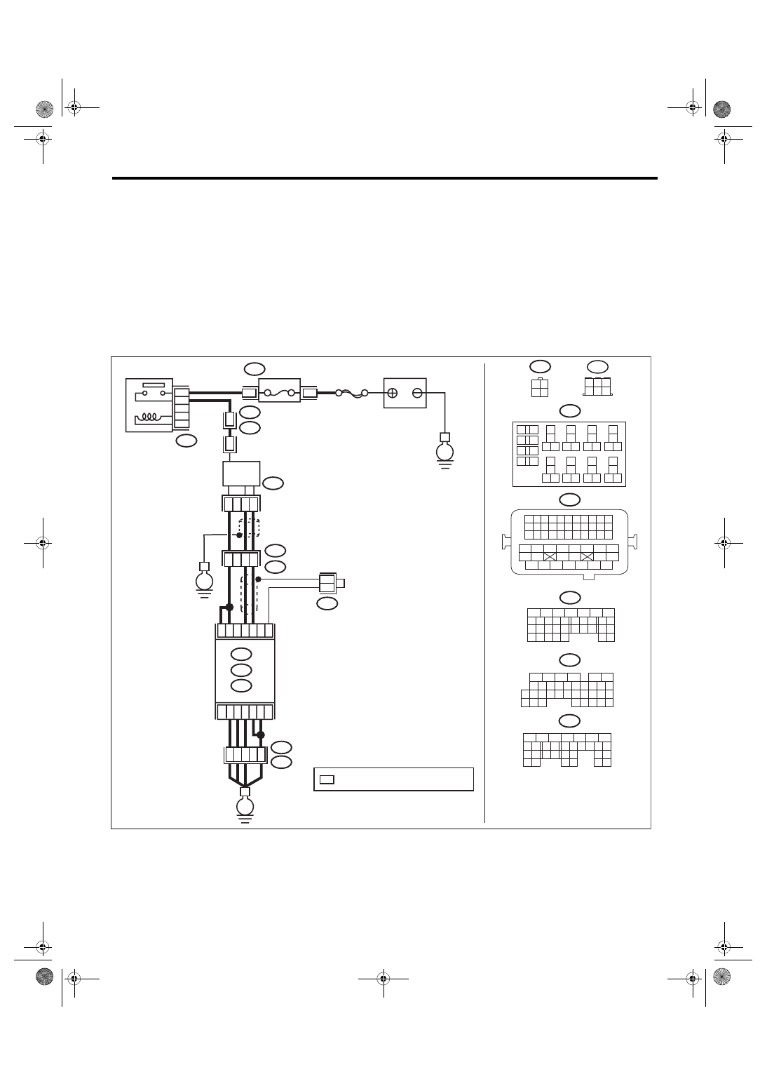
AD:DTC P0131 O2 SENSOR CIRCUIT LOW VOLTAGE (BANK 1 SENSOR 1)
DTC DETECTING CONDITION:
• Immediately at fault recognition
• GENERAL DESCRIPTION <Ref. to GD(H4DOTC)-67, DTC P0131 O2 SENSOR CIRCUIT LOW VOLT-
AGE (BANK 1 SENSOR 1), Diagnostic Trouble Code (DTC) Detecting Criteria.>
CAUTION:
After servicing or replacing faulty parts, perform Clear Memory Mode <Ref. to EN(H4DOTC)(diag)-63,
OPERATION, Clear Memory Mode.>, and Inspection Mode <Ref. to EN(H4DOTC)(diag)-49, PROCE-
WIRING DIAGRAM:
• Models without SI-DRIVE <Ref. to WI-32, WITHOUT SI-DRIVE, WIRING DIAGRAM, Engine Electrical
ECM
B138
6
4 5
3
2
1
E22
1
2
3
15
43
26
B21
E2
44
2
E2
B21
1 2
3 4
E22
B220
13
14
15 16
17
27
24
25
26
20
21
22
23
29
30
31
28
32 35
33
34
37
38
39
36
40
8
9
10
11 12
1
2
5
3
4
7
6
19
18
2
1
B220
15A
9
10
11
12
B220
D:
5
6
7
8
2
1
9
4
3
10
22 23
11 12 13 14 15
24 25
26
16 17
18 19 20 21
27
28 29
30 31
B137
C: B136
16
10 11 12 13 14 15
25
24
30
9
8
7
17 18 19 20
28
21 22 23
29
32
31
1
2
3
4
5
6
27
26
33 34 35
*
*
*
B138
D1
36
A4
40
34
35
B21
E2
D3
A6
A3
A:
54
52 53
50 51
48 49
46 47
45
44
42 43
40 41
38 39
36 37
34 35
33
32
31
30
29
28
27
26
25
24
23
22
21
20
11
10
9
19
18
17
16
8
7
6
5
15
14
13
12
4
3
2
1
D: B137
C: B136
A:
31
30
32
29
34
33
21
20
19
18
17
16
28
27
26
15
14
13
12
11
25
23
22
24
10
3
4
9
1
2
8
7
6
5
B134
B21
B134
C9
C19
C1
8
C6
C5
EN-08720
E
E
E
SBF-5
BATTERY
: TERMINAL No. OPTIONAL ARRANGEMENT
A/F, OXYGEN SENSOR
RELAY
FUSE
(RELAY BLOCK)
FRONT OXYGEN (A/F)
SENSOR
EN(H4DOTC)(diag)-151
Diagnostic Procedure with Diagnostic Trouble Code (DTC)
ENGINE (DIAGNOSTICS)
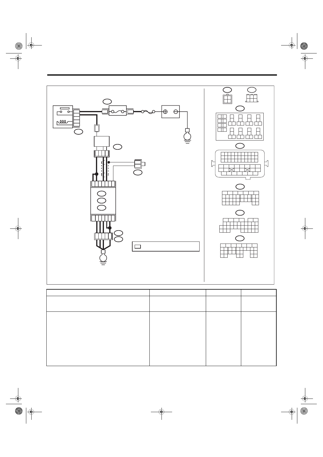
• Models with SI-DRIVE <Ref. to WI-48, WITH SI-DRIVE, WIRING DIAGRAM, Engine Electrical System.>
Step
Check
Yes
No
1
CHECK FRONT OXYGEN (A/F) SENSOR
CONNECTOR AND COUPLING CONNEC-
TOR.
Has water entered the connec-
tor?
Completely
remove any water
inside.
2
CHECK HARNESS BETWEEN ECM AND
FRONT OXYGEN (A/F) SENSOR CONNEC-
TOR.
1) Turn the ignition switch to OFF.
2) Disconnect the connectors from ECM and
front oxygen (A/F) sensor connector.
3) Measure the resistance between ECM con-
nector and chassis ground.
Connector & terminal
(B136) No. 19 — Chassis ground:
(B136) No. 18 — Chassis ground:
Is the resistance 1 MΩ or
more?
Repair the short
circuit to ground in
harness between
ECM connector
and front oxygen
(A/F) sensor con-
nector.
ECM
B138
6
4 5
3
2
1
1
2
3
4
B220
13
14
15 16
17
27
24
25
26
20
21
22
23
29
30
31
28
32 35
33
34
37
38
39
36
40
8
9
10
11 12
1
2
5
3
4
7
6
19
18
2
1
B220
15A
9
10
11
12
B220
D:
5
6
7
8
2
1
9
4
3
10
22 23
11 12 13 14 15
24 25
26
16 17
18 19 20 21
27
28 29
30 31
B137
C: B136
16
10 11 12 13 14 15
25
24
30
9
8
7
17 18 19 20
28
21 22 23
29
32
31
1
2
3
4
5
6
27
26
33 34 35
*
*
*
B138
D1
36
D3
A4
40
34
35
B21
E2
A6
A3
A:
54
52 53
50 51
48 49
46 47
45
44
42 43
40 41
38 39
36 37
34 35
33
32
31
30
29
28
27
26
25
24
23
22
21
20
11
10
9
19
18
17
16
8
7
6
5
15
14
13
12
4
3
2
1
D: B137
C: B136
A:
31
30
32
29
34
33
21
20
19
18
17
16
28
27
26
15
14
13
12
11
25
23
22
24
10
3
4
9
1
2
8
7
6
5
B134
B379
B21
B379
4
2
3
1
B134
C9
C19
C1
8
C6
C5
EN-08721
SBF-5
E
E
FRONT OXYGEN (A/F)
SENSOR
BATTERY
: TERMINAL No. OPTIONAL ARRANGEMENT
A/F, OXYGEN SENSOR
RELAY
FUSE
(RELAY BLOCK)
Нет комментариевНе стесняйтесь поделиться с нами вашим ценным мнением.
Текст