Subaru Impreza 3 / Impreza WRX / Impreza WRX STI. Service manual — part 347
GD(H4DOTC)-140
Diagnostic Trouble Code (DTC) Detecting Criteria
GENERAL DESCRIPTION
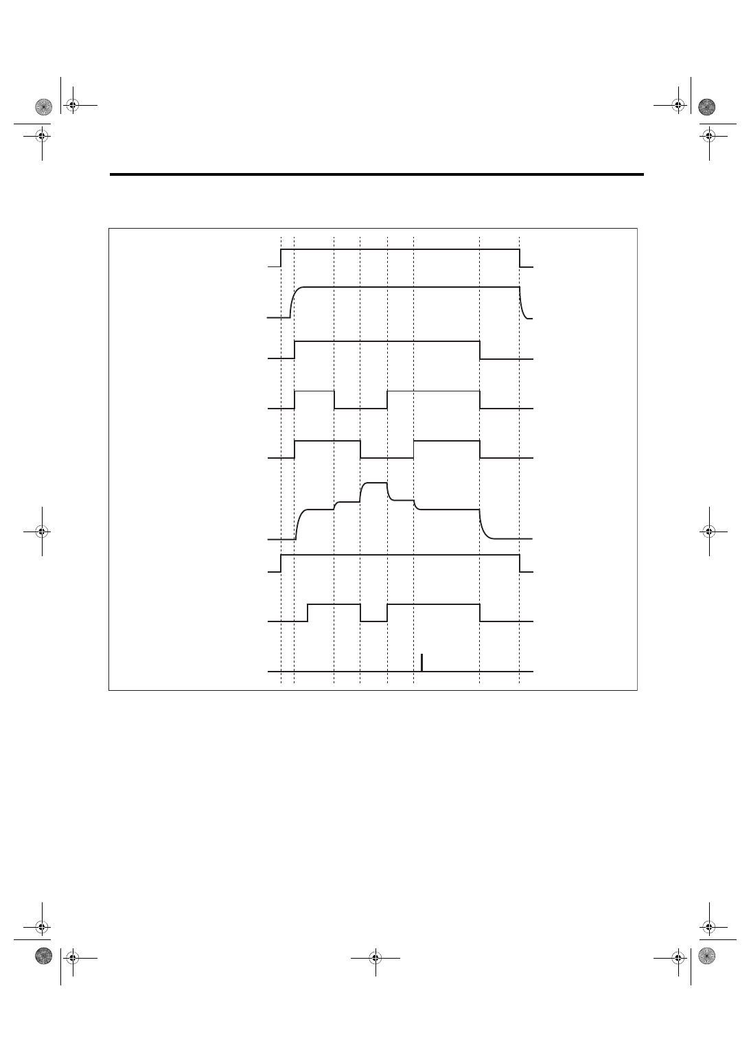
4. DIAGNOSTIC METHOD
Measure secondary air delivery pipe pressure, pulse of secondary air delivery pipe pressure and secondary
air pipe airflow amount.
(1)
IG
(6)
Secondary air delivery pipe pres-
sure (psi)
(10) Barometric pressure (Pas) mea-
surement before secondary air
control
(2)
Ne
(7)
Diagnosis enable condition
(11) Right bank all closed pressure
(P0R) measurement
(3)
Secondary air pump operating
status
(8)
Pump supply pressure check
(judgment)
(12) Both banks all closed pressure
(P0RL) measurement
(4)
E-COMB valve (right hand) status
(9)
Flow amount check (judgment)
(13) Left bank all closed pressure
(P0L) measurement
(5)
E-COMB valve (left hand) status
(2)
(7)
(8)
(6)
(12)
(11)
(10)
(13)
(9)
EN-05591
(3)
ON
OFF
(1)
ON
OFF
(4)
OPEN
CLOSE
(5)
OPEN
CLOSE
GD(H4DOTC)-141
Diagnostic Trouble Code (DTC) Detecting Criteria
GENERAL DESCRIPTION
Pump supply pressure check
Perform the system function diagnosis with how much the pressure rises when the secondary air pump is
turned from OFF to ON.
Judge as NG if delivery pipe pressure does not rise though it should when the secondary air pump turns OFF
→ ON.
•
Abnormality Judgment
If the duration of time while the following conditions are met is longer than the time indicated, judge as NG.
Time Needed for Diagnosis: 2000 ms + 2800 ms
Malfunction Indicator Light Illumination: Illuminates when malfunction occurs in 2 continuous driving cy-
cles.
•
Normality Judgment
Judge as OK and clear the NG if the continuous time while the following conditions are established is more
than the predetermined time.
Time Needed for Diagnosis: 2000 ms + 2800 ms
Combination valve both closed pulse diagnosis
Perform open stuck diagnosis of both combination valves using delivery pipe pressure pulse when both com-
bination valves are closed. Determine which side of valves is stuck open by comparing secondary air flow
amount when RH combination valve is closed with that when LH combination valve is closed.
Calculate voltage pulse of the pump delivery pipe pressure when both combination valves are closed. The
calculation should be small because there is no pulse from supply pipe pressure with both combination
valves closed. When the calculation is large, determine that either of the combination valves is stuck open.
Determine which side of valves is stuck open by comparing secondary air flow amount when the RH combi-
nation valve is closed with that when the LH combination valve is closed. Air flow amount is larger on the
open stuck valve.
•
Abnormality Judgment
If the duration of time while the following conditions are met is longer than the time indicated, judge as NG.
Time Needed for Diagnosis: 4000 ms + 992 ms + 992 ms + 992 ms
Malfunction Indicator Light Illumination: Illuminates when malfunction occurs in 2 continuous driving cy-
cles.
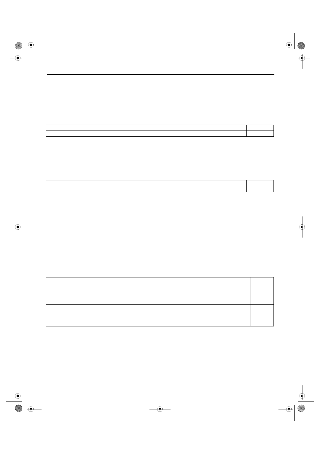
Judgment Value
Malfunction Criteria
Threshold Value
DTC
Secondary air supply pipe pressure (after barometric pressure compensation)
< 0.9 kPa (7 mmHg, 0.3 inHg)
P0410
Judgment Value
Malfunction Criteria
Threshold Value
DTC
Secondary air supply pipe pressure (after barometric pressure compensation)
≥ 0.9 kPa (7 mmHg, 0.3 inHg)
P0410
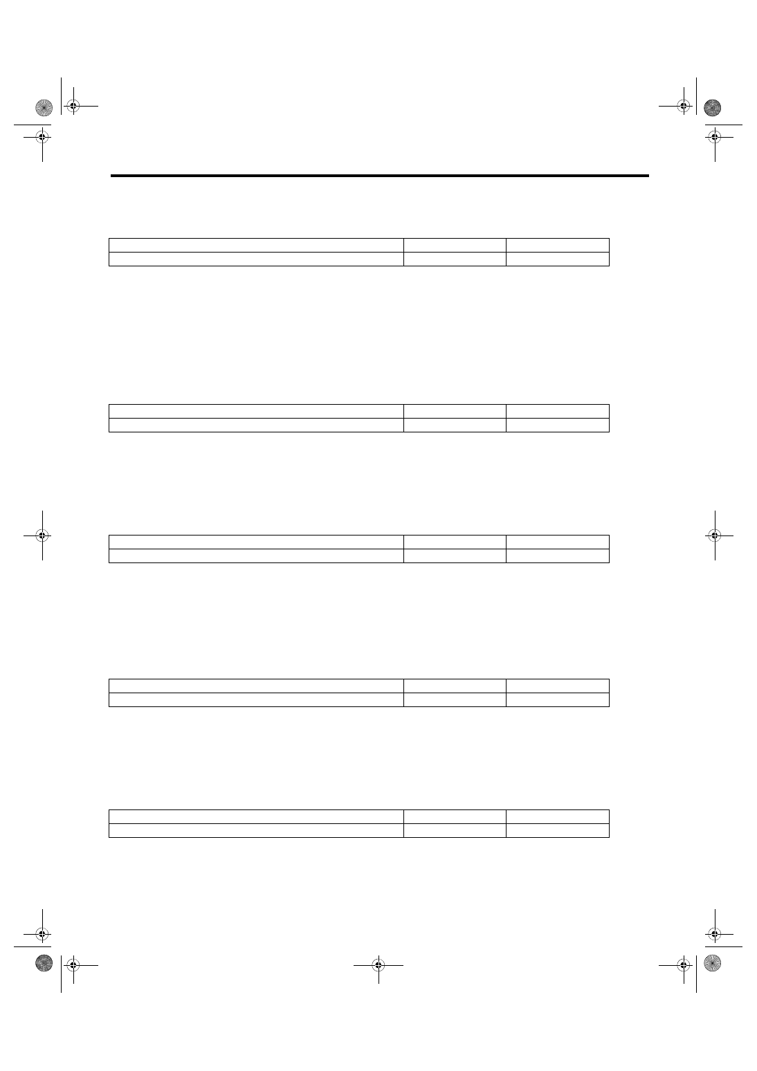
Judgment Value
Malfunction Criteria
Threshold Value
DTC
Pulse calculation value when both combination valves
are closed
> Value of Map 3
P2440
Air flow amount when the right bank is closed (value
from Map 4)
≥ Air flow amount when the left bank is closed (value
from Map 5)
Pulse calculation value when both combination valves
are closed
> Value of Map 3
P2442
Air flow amount when the left bank is closed (value from
Map 5)
> Air flow amount when the right bank is closed (value
from Map 4)
GD(H4DOTC)-142
Diagnostic Trouble Code (DTC) Detecting Criteria
GENERAL DESCRIPTION
•
Normality Judgment
Judge as OK and clear the NG if the continuous time while the following conditions are established is more
than the predetermined time.
Time Needed for Diagnosis: 4000 ms + 992 ms + 992 ms + 992 ms
Combination valve changeover pressure diagnosis
Perform the RH combination valve stuck closed diagnosis with the variation of delivery pipe pressure when
the RH combination valve turns closed → open.
Delivery pipe pressure should vary when the RH combination valve turns closed → open. When the variation
is small, determine that the RH combination valve is stuck closed.
•
Abnormality Judgment
If the duration of time while the following conditions are met is longer than the time indicated, judge as NG.
Time Needed for Diagnosis: 4000 ms + 992 ms + 992 ms + 992 ms
Malfunction Indicator Light Illumination: Illuminates when malfunction occurs in 2 continuous driving cy-
cles.
•
Normality Judgment
Judge as OK and clear the NG if the continuous time while the following conditions are established is more
than the predetermined time.
Time Needed for Diagnosis: 4000 ms + 992 ms + 992 ms + 992 ms
Perform the LH combination valve stuck closed diagnosis with the variation of delivery pipe pressure when
the LH combination valve turns open → closed.
Delivery pipe pressure should vary when the LH combination valve turns open → closed. When the variation
is small, determine that the LH combination valve is stuck closed.
•
Abnormality Judgment
If the duration of time while the following conditions are met is longer than the time indicated, judge as NG.
Time Needed for Diagnosis: 4000 ms + 992 ms + 992 ms + 992 ms
Malfunction Indicator Light Illumination: Illuminates when malfunction occurs in 2 continuous driving cy-
cles.
•
Normality Judgment
Judge as OK and clear the NG if the continuous time while the following conditions are established is more
than the predetermined time.
Time Needed for Diagnosis: 4000 ms + 992 ms + 992 ms + 992 ms
Judgment Value
Malfunction Criteria
Threshold Value
DTC
Pulse calculation value when both combination valves are closed
≤ Value of Map 3
P2440, P2442
Judgment Value
Malfunction Criteria
Threshold Value
DTC
Pressure variation value when the RH combination valve is switched
< Value of Map 6
P2441
Judgment Value
Malfunction Criteria
Threshold Value
DTC
Pressure variation value when the RH combination valve is switched
≥ Value of Map 6
P2441
Judgment Value
Malfunction Criteria
Threshold Value
DTC
Pressure variation value when the LH combination valve is switched
< Value of Map 7
P2443
Judgment Value
Malfunction Criteria
Threshold Value
DTC
Pressure variation value when the LH combination valve is switched
≥ Value of Map 7
P2443
GD(H4DOTC)-143
Diagnostic Trouble Code (DTC) Detecting Criteria
GENERAL DESCRIPTION
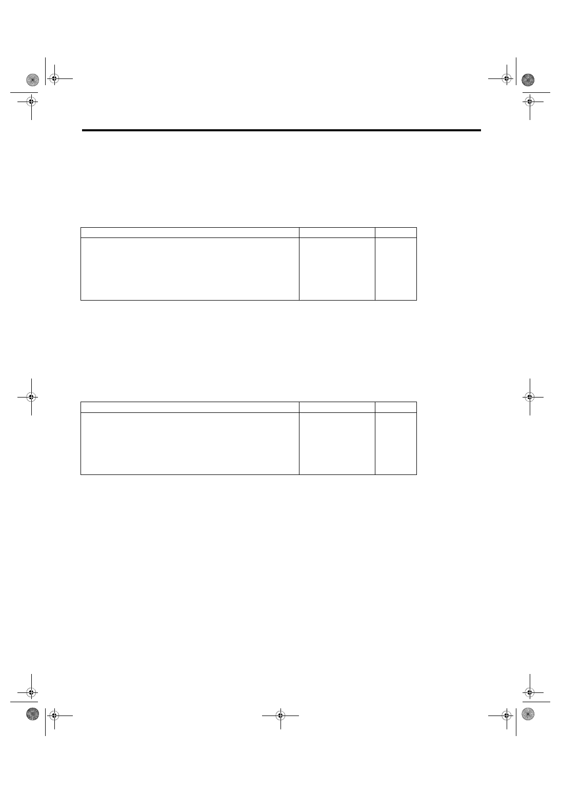
Overflow diagnosis
Perform secondary air system flow abnormality diagnosis using both sides of combination valves secondary
air amount when both are closed.
Judge as secondary air system flow abnormality either if there is excessive secondary air flow amount with
the RH combination valve closed, or if there is excessive secondary air flow amount with the LH combination
valve closed.
•
Abnormality Judgment
If the duration of time while the following conditions are met is longer than the time indicated, judge as NG.
P0RL: Both banks all closed pressure
P0R: Right bank all closed pressure
P0L: Left bank all closed pressure
Time Needed for Diagnosis: 4000 ms + 992 ms + 992 ms + 992 ms
Malfunction Indicator Light Illumination: Illuminates when malfunction occurs in 2 continuous driving cy-
cles.
•
Normality Judgment
Judge as OK and clear the NG if the continuous time while the following conditions are established is more
than the predetermined time.
P0RL: Both banks all closed pressure
P0R: Right bank all closed pressure
P0L: Left bank all closed pressure
Time Needed for Diagnosis: 4000 ms + 992 ms + 992 ms + 992 ms
Judgment Value
Malfunction Criteria
Threshold Value
DTC
Air flow amount when the right bank is closed (value from Map 4)
> Value of Map 8
P0411
or
Air flow amount when the left bank is closed (value from Map 5)
> Value of Map 9
Voltage at P0RL measurement – Voltage at P0R measurement
≤ 4 V
Voltage at P0RL measurement – Voltage at P0L measurement
≤ 4 V
Judgment Value
Malfunction Criteria
Threshold Value
DTC
Air flow amount when the right bank is closed (value from Map 4)
≤ Value of Map 8
P0411
or
Air flow amount when the left bank is closed (value from Map 5)
≤ Value of Map 9
Voltage at P0RL measurement – Voltage at P0R measurement
≤ 4 V
Voltage at P0RL measurement – Voltage at P0L measurement
≤ 4 V
Нет комментариевНе стесняйтесь поделиться с нами вашим ценным мнением.
Текст