Subaru Legacy (2005 year). Service manual — part 128

EN(H4SO 2.0)(diag)-101
ENGINE (DIAGNOSTICS)
Diagnostic Procedure with Diagnostic Trouble Code (DTC)
Step
Check
Yes
No
1
CHECK SENSOR OUTPUT.
1) Turn the ignition switch to ON.
2) Read the data of main throttle sensor signal
using Subaru Select Monitor.
NOTE:
For detailed operation procedure, refer to
“READ CURRENT DATA FOR ENGINE”. <Ref.
to EN(H4SO 2.0)(diag)-25, Subaru Select Mon-
itor.>
Is the voltage less than 4.63
V?
2
CHECK POOR CONTACT.
Check poor contact in connector between
ECM and electronic throttle control.
Is there poor contact in con-
nector between ECM and elec-
tronic throttle control?
Repair the poor
contact.
Temporary poor
contact occurred,
but it is normal at
present.
3
CHECK HARNESS BETWEEN ECM AND
ELECTRONIC THROTTLE CONTROL.
1) Turn the ignition switch to OFF.
2) Disconnect the connector from ECM.
3) Disconnect the connectors from electronic
throttle control.
4) Measure the resistance between ECM con-
nector and electronic throttle control connector.
Connector & terminal
(B137) No. 23 — (E78) No. 5:
LHD model
(B136) No. 18 — (E78) No. 1:
RHD model
(B136) No. 18 — (E78) No. 3:
Is the resistance less than 1
Ω?
Repair the open
circuit of harness
connector.
4
CHECK HARNESS BETWEEN ECM AND
ELECTRONIC THROTTLE CONTROL.
1) Connect the ECM connector.
2) Measure the resistance between electronic
throttle control connector and engine ground.
Connector & terminal
LHD model
(E78) No. 1 — Engine ground:
RHD model
(E78) No. 3 — Engine ground:
Is the resistance less than 1
Ω?
Repair the poor
contact in ECM
connector.
Replace the ECM
if defective. <Ref.
to FU(H4SO 2.0)-
34, Engine Con-
trol Module
(ECM).>
5
CHECK SENSOR OUTPUT POWER SUP-
PLY.
Measure the voltage between electronic throt-
tle control connector and engine ground.
Connector & terminal
(E78) No. 5 (+) — Engine ground (
−
):
Is the voltage less than 10 V?
Repair the battery
short circuit of har-
ness between
ECM connector
and electronic
throttle control
connector.
6
CHECK HARNESS BETWEEN ECM AND
ELECTRONIC THROTTLE CONTROL.
1) Turn the ignition switch to OFF.
2) Disconnect the connector from ECM.
3) Measure the resistance between ECM con-
nectors.
Connector & terminal
(B137) No. 23 — (B136) No. 17:
Is the resistance more than 1
M
Ω?
Repair the poor
contact in harness.
Replace the elec-
tronic throttle con-
trol.
Repair the short
circuit to sensor
power supply.
EN(H4SO 2.0)(diag)-102
ENGINE (DIAGNOSTICS)
Diagnostic Procedure with Diagnostic Trouble Code (DTC)
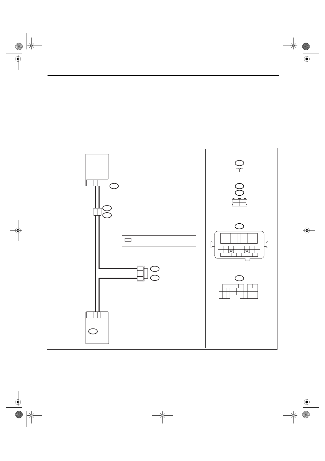
N: DTC P0125 INSUFFICIENT COOLANT TEMPERATURE FOR CLOSED LOOP
FUEL CONTROL
DTC DETECTING CONDITION:
Detects when malfunction occurs in 2 continuous driving cycles.
TROUBLE SYMPTOM:
Engine would not return to idling.
CAUTION:
After repair or replacement of faulty parts, perform Clear Memory Mode <Ref. to EN(H4SO 2.0)(diag)-
38, OPERATION, Clear Memory Mode.> and Inspection Mode <Ref. to EN(H4SO 2.0)(diag)-32, PRO-
CEDURE, Inspection Mode.>.
WIRING DIAGRAM:
EN-03479
18
22
19
8
B136
ECM
1
2
E2
B21
E8
ENGINE
COOLANT
TEMPERATURE
SENSOR
E8
B21
1 2 3 4
5 6 7 8
1 2 3 4
12 13 14 15
5 6 7 8
16 17 18 19
9 10 11
20 21 22
23 24 25 26 27 28 29 30 31 32 33
35
34
37
36
39
38
41
40
43
42
44
45
47
46
49
48
51
50
53
52
54
B136
5
6
7 8
2
1
9
4
3
10
24
22 23
25
11 12 13 14 15
26 27
28
16
17 18 19 20 21
33 34
29
32
30
31
35
1 2
B138
B83
B83
:LHD
B138 :RHD
*
*
*
: TERMINAL No. RANDOM ARRANGEMENT
AMONG 1,2,5, AND 6

EN(H4SO 2.0)(diag)-103
ENGINE (DIAGNOSTICS)
Diagnostic Procedure with Diagnostic Trouble Code (DTC)
Step
Check
Yes
No
1
CHECK ANY OTHER DTC ON DISPLAY.
Is any other DTC displayed?
Check DTC using
“List of Diagnostic
Trouble Code
(DTC)”. <Ref. to
EN(H4SO
2.0)(diag)-64, List
of Diagnostic Trou-
ble Code (DTC).>
NOTE:
In this case, it is
not necessary to
inspect DTC
P0125.
2
CHECK THERMOSTAT.
Does the thermostat remain
opened?
Replace the ther-
mostat. <Ref. to
CO(H4SO 2.0)-18,
Thermostat.>
Replace the
engine coolant
temperature sen-
sor. <Ref. to
FU(H4SO 2.0)-20,
Engine Coolant
Temperature Sen-
sor.>
EN(H4SO 2.0)(diag)-104
ENGINE (DIAGNOSTICS)
Diagnostic Procedure with Diagnostic Trouble Code (DTC)
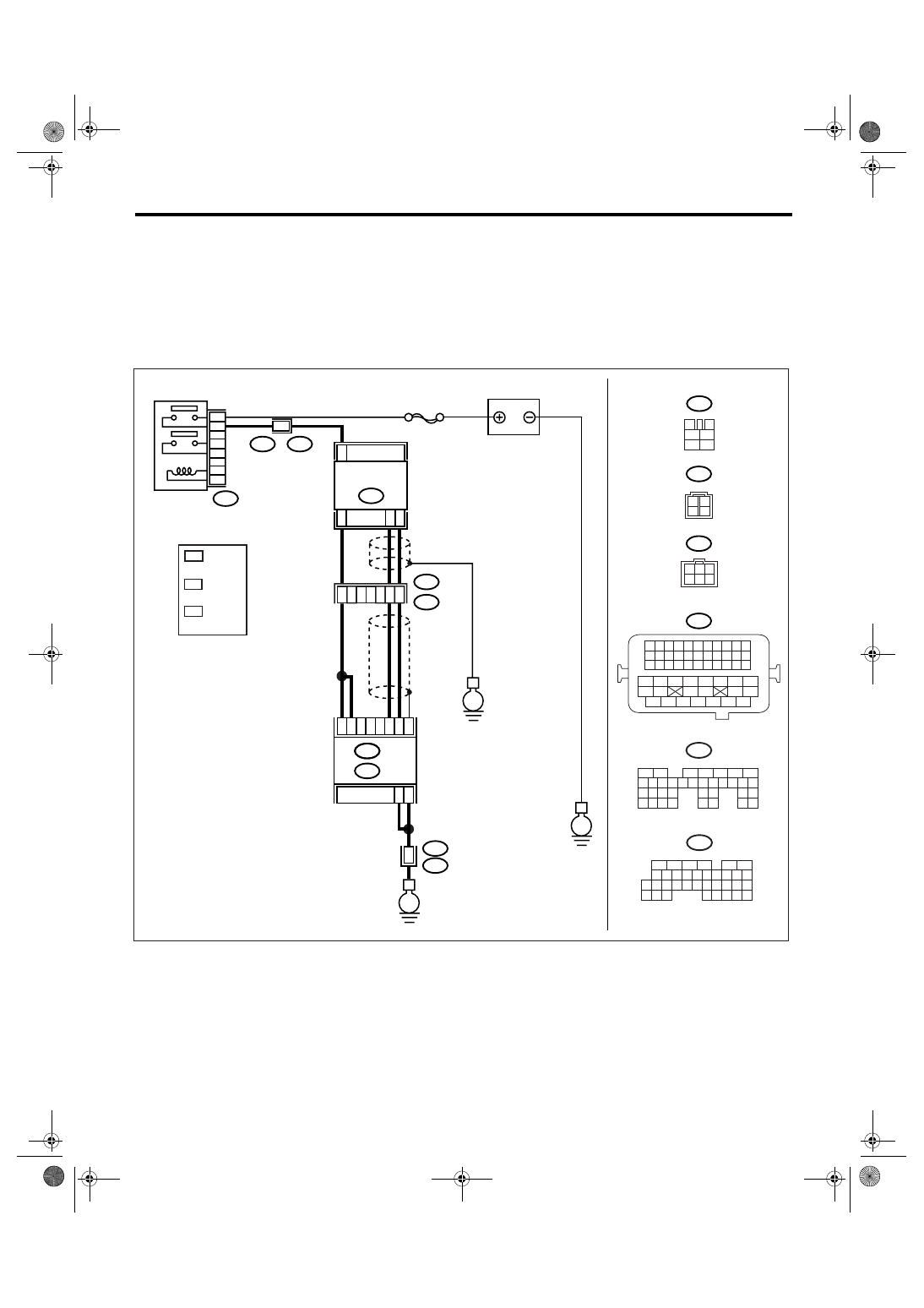
O: DTC P0130 O2 SENSOR CIRCUIT (BANK 1 SENSOR 1)
DTC DETECTING CONDITION:
Immediately at fault recognition
CAUTION:
After repair or replacement of faulty parts, perform Clear Memory Mode <Ref. to EN(H4SO 2.0)(diag)-
38, OPERATION, Clear Memory Mode.> and Inspection Mode <Ref. to EN(H4SO 2.0)(diag)-32, PRO-
CEDURE, Inspection Mode.>.
WIRING DIAGRAM:
EN-03475
3
4
1
2
5
6
B47
SBF-5
E
B47
E24
5
3
4
6
2
1
C34
C35
C33
B3
B2
B1
B135
E
B5
B6
52
B21
E2
B21
E2
50
51
3
4
E2
B21
E
B21
1 2 3 4
12 13 14 15
5 6 7 8
16 17 18 19
9 10 11
20 21 22
23 24 25 26 27 28 29 30 31 32 33
35
34
37
36
39
38
41
40
43
42
44
45
47
46
49
48
51
50
53
52
54
E24
ECM
BATTERY
FRONT OXYGEN
(A/F) SENSOR
MAIN RELAY
B136
B:
C:
1
2
3
4
B135
5
6
7
8
2
1
9
4
3
10
24
22 23
25
11 12 13 14 15
26 27
28
16 17 18 19
20 21
29 30 31
32 33
34 35
B:
B136
5
6
7 8
2
1
9
4
3
10
24
22 23
25
11 12 13 14 15
26 27
28
16
17 18 19 20 21
33 34
29
32
30
31
35
C:
E24
3
2
*
1
*
*
3
LHD : 4
RHD : 1
*
1
*
*
2
3
3
1
6 5 4
2
: RHD
: LHD
LHD : 1
RHD : 4
LHD : 2
RHD : 6
Нет комментариевНе стесняйтесь поделиться с нами вашим ценным мнением.
Текст