Subaru Legacy (2005 year). Service manual — part 100
SC(H4SO 2.0)-11
STARTING/CHARGING SYSTEMS
Starter
13) Connect the connector to terminal M of switch
assembly.
E: INSPECTION
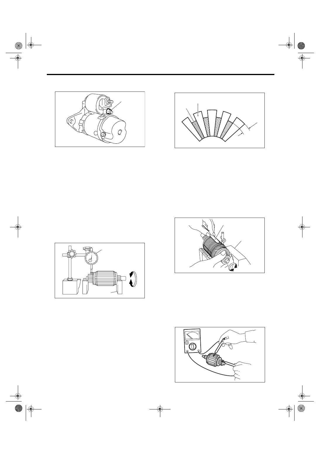
1. ARMATURE
1) Check the commutator for any sign of burns of
rough surfaces or stepped wear. If wear is of a mi-
nor nature, correct it by using sand paper.
2) Run-out test
Check the commutator for run-out, and then re-
place if it exceeds the limit.
Commutator run-out:
Standard
0.05 mm (0.0020 in)
Service limit
Less than 0.10 mm (0.0039 in)
3) Depth of segment mold
Check the depth of segment mold.
Depth of segment mold:
0.5 mm (0.020 in)
4) Armature short-circuit test
Check the armature for short-circuit by placing it on
growler tester. Hold an iron sheet against the arma-
ture core while slowly rotating the armature. A
short-circuited armature will cause the iron sheet to
vibrate and to be attracted to core. If the iron sheet
is attracted or vibrates, the armature, which is
short-circuited, must be replaced or repaired.
5) Armature ground test
Using a circuit tester, touch one probe to the com-
mutator segment and the other to shaft. No conti-
nuity is normal. If there is continuity, the armature is
grounded.
Replace the armature if it is grounded.
(A) Terminal M
(A) Dial gauge
(B) V-block
SC-02094
(A)
SC-00021
(A)
(B)
(A) Depth of mold
(B) Segment
(C) Mold
(A) Iron sheet
(B) Growler tester
(C)
(B)
(A)
SC-00022
(A)
(B)
SC-00023
SC-00024
SC(H4SO 2.0)-12
STARTING/CHARGING SYSTEMS
Starter
2. YOKE
Make sure the pole is set in position.
3. OVERRUNNING CLUTCH
Inspect the teeth of pinion for wear and damage.
Replace if it is damaged. Rotate the pinion in the
right direction of rotation (counterclockwise). It
should rotate smoothly. But in the opposite direc-
tion, it should be locked.
CAUTION:
Do not clean the overrunning clutch with oil to
prevent grease from flowing out.
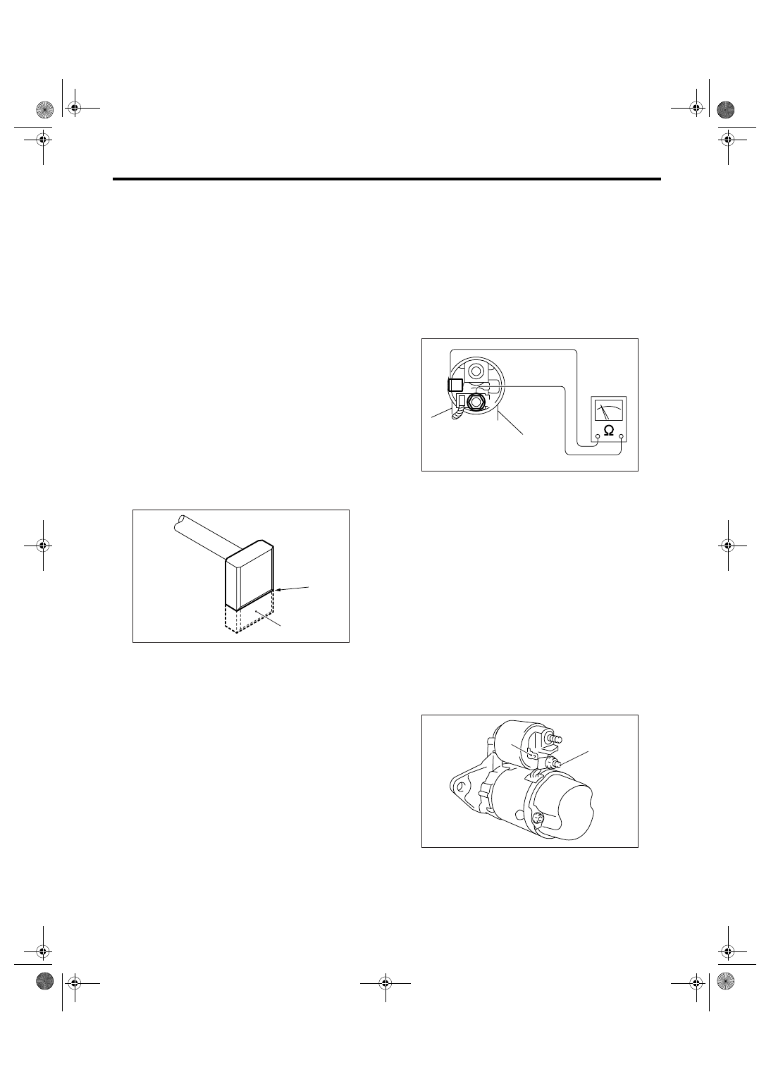
4. BRUSH AND BRUSH HOLDER
1) Brush length
Measure the brush length, and then replace if it ex-
ceeds the service limit.
Replace if abnormal wear or cracks are noticed.
Brush length:
Standard
12.3 mm (0.484 in)
Service limit
7.0 mm (0.276 in)
2) Brush movement
Be sure the brush moves smoothly inside brush
holder.
3) Brush spring force
Measure the brush spring force with a spring scale.
If it is less than the service limit, replace the brush
holder.
Brush spring force:
Standard
15.9 — 19.5 N (1.62 — 1.99 kgf, 3.57 — 4.38
lbf) (when new)
Service limit
2.5 N (0.25 kgf, 18.24 lbf)
5. SWITCH ASSEMBLY
Be sure there is continuity between the terminals S
and M, and between terminal S and ground. Use a
circuit tester (set in “ohm”).
Also check to be sure there is no continuity be-
tween terminal M and B.
Terminal / Specified resistance:
S — M / Less than 1
Ω
S — Ground / Less than 1
Ω
M — B / More than 1 M
Ω
6. SWITCH ASSEMBLY OPERATION
1) Using a lead wire, connect the terminal S of
switch assembly to positive terminal of battery, and
starter body to ground terminal of battery. The pin-
ion should be forced endwise on shaft.
CAUTION:
With the pinion forced endwise on shaft, starter
motor can sometimes rotate because current
flows, through pull-in coil, to motor. This is not
a problem.
2) Disconnect the connector from terminal M. Then
using a lead wire, connect the positive terminal of
battery and terminal M and ground terminal to start-
er body.
In this test set up, the pinion should return to its
original position even when it is pulled out with a
screwdriver.
(A) Service limit line
(B) Brush
SC-00102
(A)
(B)
(A) Terminal S
(B) Terminal M
SC-00075
B
M
S
SC-00076
(B)
(A)
SC(H4SO 2.0)-13
STARTING/CHARGING SYSTEMS
Starter
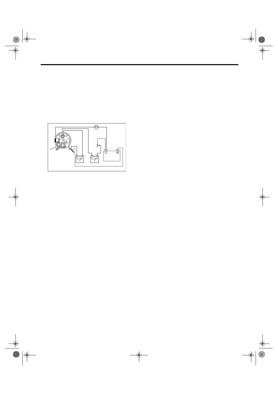
7. PERFORMANCE TEST
The starter should be submitted to performance
tests whenever it has been overhauled, to assure
its satisfactory performance when installed on the
engine.
Three performance tests, no-load test, load test,
and lock test, are presented here; however, if the
load test and lock test cannot be performed, carry
out at least the no-load test.
For these performance tests, use the circuit shown
in figure.
1) No-load test
With switch on, adjust the variable resistance for
the voltage to obtain 11 V, read the ammeter and
measure the starter speed. Compare these values
with the standard.
No-load test (standard):
Voltage / Current
MT model
11 V / 95 A or less
AT model
11 V / 90 A or less
Rotating speed
MT model
More than 2,500 rpm
AT model
More than 2,000 rpm
2) Load test
Apply the specified braking torque to starter. The
condition is satisfactory if the current draw and
starter speed are within standard.
Load test (standard):
Voltage / Load
MT model
7.5 V / 8.84 N
⋅
m (0.90 kgf-m, 6.5 ft-lb)
AT model
7.7 V / 16.7 N
⋅
m (1.70 kgf-m, 12.3 ft-lb)
Current / Speed
MT model
More than 300 A / 870 rpm
AT model
More than 400 A / 710 rpm
3) Lock test
With the starter stalled, or not rotating, measure the
torque developed and current draw when the volt-
age is adjusted to standard voltage.
Lock test (standard):
Voltage / Current
MT model
4 V / 680 A or less
AT model
3.5 V / 960 A or less
Torque
MT model
17 N
⋅
m (1.73 kgf-m, 12.5 ft-lb)
AT model
31 N
⋅
m (3.16 kgf-m, 22.9 ft-lb)
(A) Variable resistor
(B) Starter body
(C) Magnetic switch
SC-00077
(A)
(B)
(C)
12V
+
A
V
B
S
M
SC(H4SO 2.0)-14
STARTING/CHARGING SYSTEMS
Generator
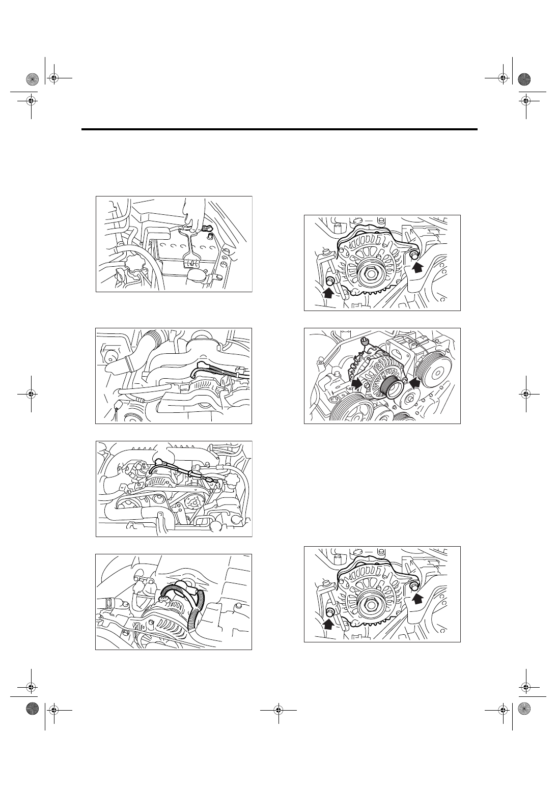
3. Generator
A: REMOVAL
1) Remove the collector cover. (Turbo model and
3.0 L Non-turbo model).
2) Disconnect the ground cable from battery.
3) Disconnect the connector and terminal from
generator.
• SOHC non-turbo model
• Turbo model
• 3.0 L non-turbo model
4) Remove the V-belt.
<Ref. to ME(H4SO 2.0)-37, FRONT SIDE BELT,
REMOVAL, V-belt.> <Ref. to ME(H4DOTC)-40,
FRONT SIDE BELT, REMOVAL, V-belt.> <Ref. to
ME(H6DO)-33, REMOVAL, V-belt.>
5) Remove the bolts which install the generator
onto bracket.
• 2.0 L model and 2.5 L non-turbo model
• 3.0 L non-turbo model
B: INSTALLATION
Install in the reverse order of removal.
Tightening torque:
25 N
⋅
m (2.5 kgf-m, 18.4 ft-lb)
CAUTION:
Check and adjust the V-belt tension.
<Ref. to ME(H4SO 2.0)-38, INSPECTION, V-
belt.> <Ref. to ME(H4DOTC)-41, INSPECTION,
V-belt.> <Ref. to ME(H6DO)-33, INSPECTION, V-
belt.>
• 2.0 L model and 2.5 L non-turbo model
IN-00203
SC-00178
ME-00830
SC-02003
SC-00179
SC-02098
SC-00179
Нет комментариевНе стесняйтесь поделиться с нами вашим ценным мнением.
Текст