Subaru Legacy (2005 year). Service manual — part 842
PS-39
POWER ASSISTED SYSTEM (POWER STEERING)
Steering Gearbox [LHD Model]
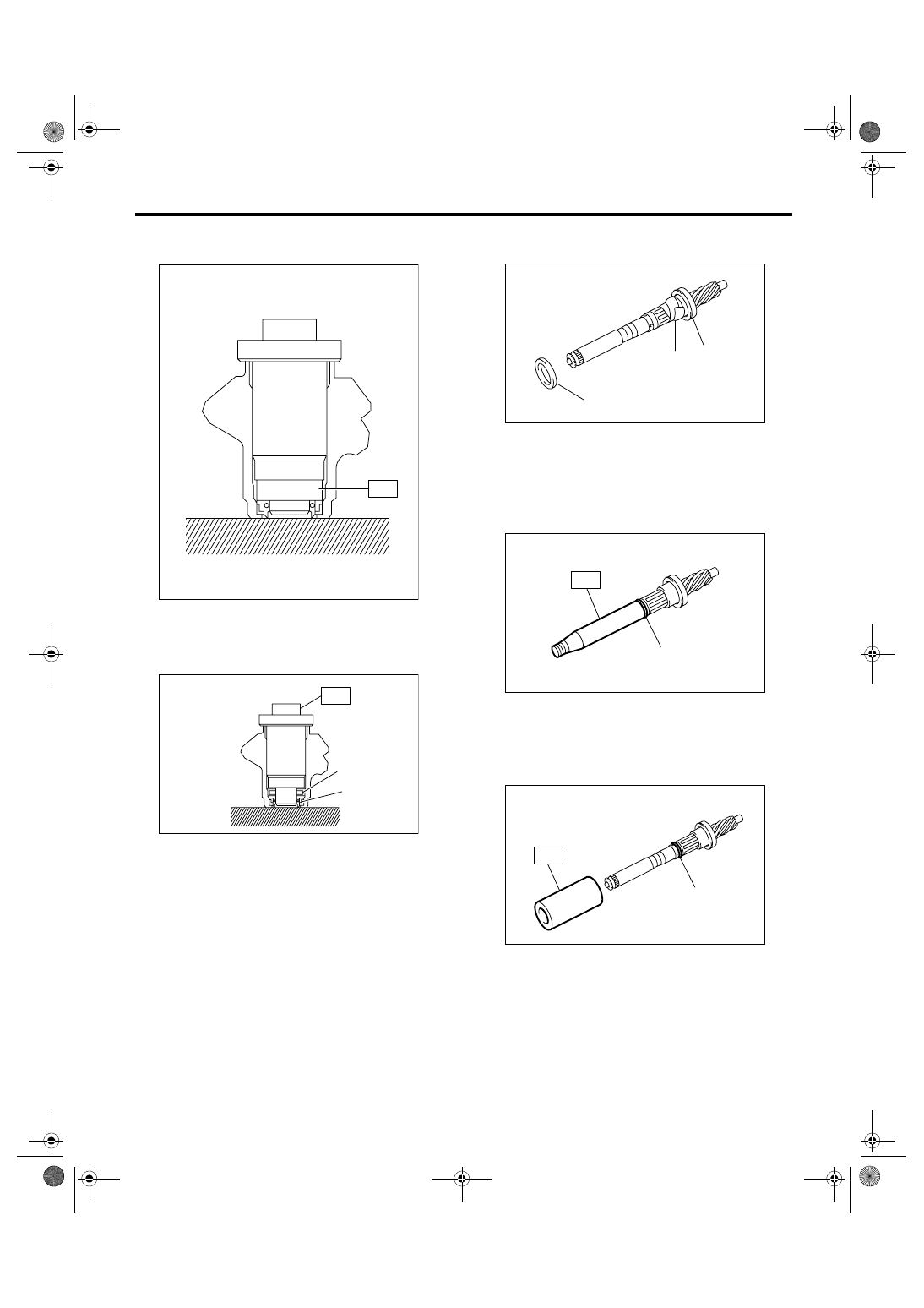
5) Press the oil seal into position using press.
ST
34199AG090 INSTALLER & REMOVER
6) Install the bearing to ST and position it to hous-
ing. Using the ST and a press, install the special
bearing in valve housing.
ST
34199AG090 INSTALLER & REMOVER
7) Apply vinyl tape to the groove of pinion.
8) Install the back-up ring and oil seal to pinion, and
then remove the vinyl tape.
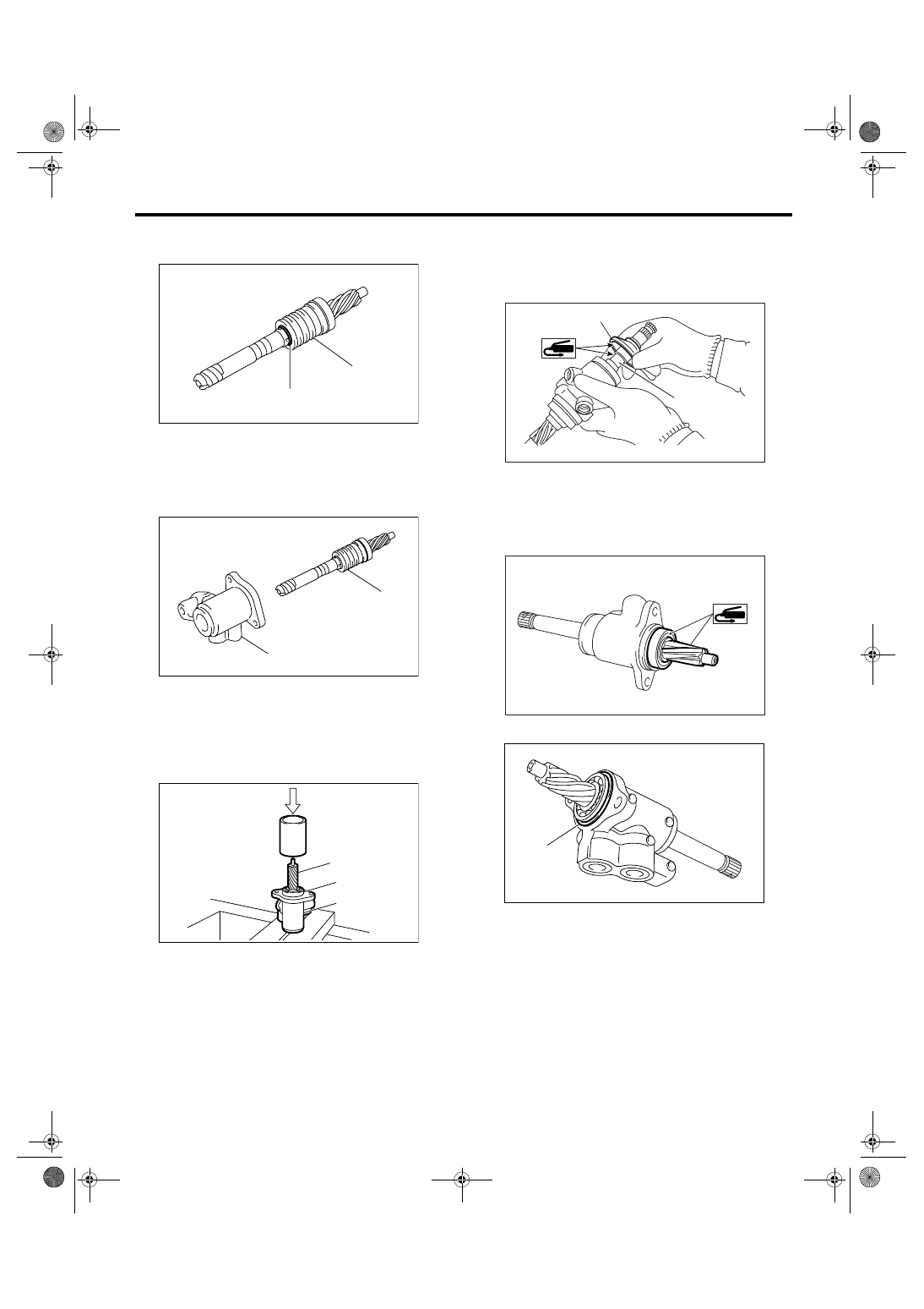
9) Install the ST to pinion, and install the seal ring.
ST
34199AG020 GUIDE
10) Remove the ST GUIDE, and form the seal ring
properly using ST FORMER.
ST
34199AG070 FORMER
11) Put vinyl tape around pinion shaft spline to pro-
tect oil seal from damage.
(1) Special bearing
(2) Oil seal
PS-00526
ST
(2)
(1)
PS-00527
ST
(1) Oil seal
(2) Vinyl tape
(3) Back-up ring
(1) Seal ring
(1) Seal ring
PS-00528
(1)
(2)
(3)
PS-00529
(1)
ST
PS-00530
ST
(1)
PS-40
POWER ASSISTED SYSTEM (POWER STEERING)
Steering Gearbox [LHD Model]
12) Install the valve to pinion, and install the snap
ring.
13) Install the pinion & valve assembly into valve
housing.
14) Using a press, push the outer race of bearing
and press-fit the pinion & valve assembly into hous-
ing.
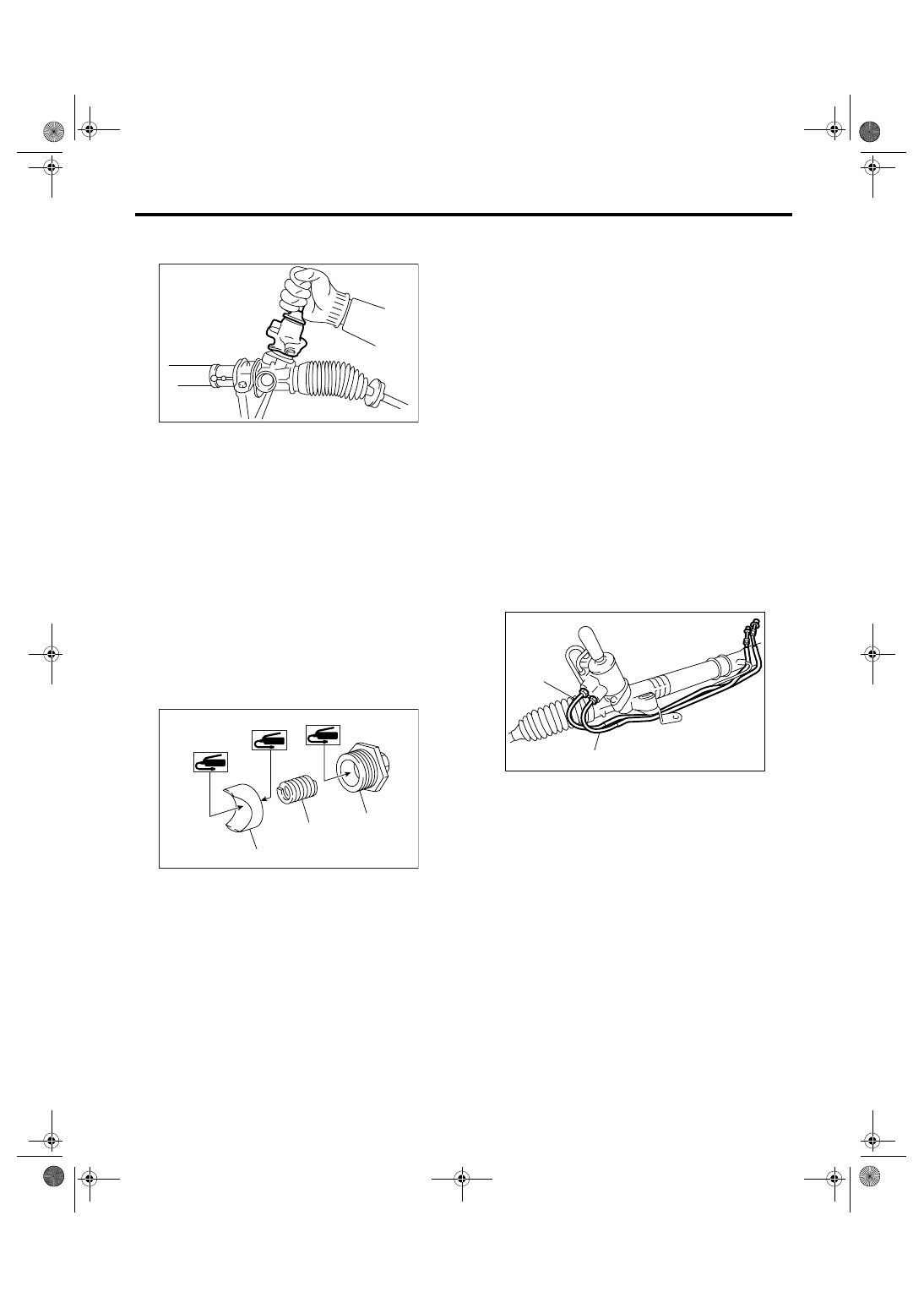
15) Apply the specified grease to dust cover.
16) Install the dust cover on valve assembly.
CAUTION:
Be sure to install the dust cover to groove of
shaft.
17) Apply genuine grease to the pinion gear and
bearing of valve assembly.
18) Install new O-ring to valve assembly.
(1) Snap ring
(2) Valve
(1) Valve housing
(2) Pinion & valve ASSY
(1) Pinion & valve ASSY
(2) Bearing
(3) Housing
PS-00531
(2)
(1)
PS-00532
(1)
(2)
PS-00533
(1)
(2)
(3)
(1) Dust cover
(2) Groove
(1) O-ring
PS-00534
(1)
(2)
PS-00165
PS-00535
(1)
PS-41
POWER ASSISTED SYSTEM (POWER STEERING)
Steering Gearbox [LHD Model]
19) Insert the valve assembly into place while fac-
ing the rack teeth toward pinion.
20) Tighten the bolts alternately to secure the valve
assembly.
Tightening torque:
25 N
⋅
m (2.5 kgf-m, 18.4 ft-lb)
CAUTION:
Be sure to alternately tighten the bolts.
21) Apply liquid gasket around the center of adjust-
ing screw threads.
Liquid gasket:
THREE BOND 1141 (Part No. 004403006)
22) Apply a coat of grease to the sliding surface of
sleeve and seating surface of spring, and then in-
sert the sleeve into steering body.
Charge the adjusting screw with grease, and then
insert the spring into adjusting screw and install on
steering body.
23) Tighten the adjusting screw to the specified
torque, then loosen it.
Tightening torque:
25 N
⋅
m (2.5 kgf-m, 18.4 ft-lb)
24) After tightening the adjusting screw with the
specified tightening torque, loosen it by 20
°.
Tightening torque:
3.9 N
⋅
m (0.4 kgf-m, 2.9 ft-lb)
25) Verify that play is within the specification. <Ref.
to PS-43, SERVICE LIMIT, INSPECTION, Steering
Gearbox [LHD Model].>
26) Install the lock nut. While holding the adjusting
screw with a wrench, tighten the lock nut using ST.
ST
926230000
SPANNER
Tightening torque (Lock nut):
25 N
⋅
m (2.5 kgf-m, 18.4 ft-lb)
NOTE:
Hold the adjusting screw with a wrench to prevent it
from turning while tightening lock nut.
27) Remove the gearbox from ST.
ST1
926200000
STAND
ST2
34199AG000 BOSS D
28) Install the four pipes on gearbox.
(1) Connect the pipes A and B to gearbox.
Tightening torque:
13 N
⋅
m (1.3 kgf-m, 9.6 ft-lb)
(2) Connect the pipes C and D to gearbox.
Tightening torque:
Pipe C: 15 N
⋅
m (1.5 kgf-m, 10.8 ft-lb)
Pipe D: 25 N
⋅
m (2.5 kgf-m, 18.4 ft-lb)
(1) Sleeve
(2) Spring
(3) Adjusting screw
PS-00143
PS-00167
(2)
(1)
(3)
(1) Pipe C
(2) Pipe D
PS-00525
(1)
(2)
PS-42
POWER ASSISTED SYSTEM (POWER STEERING)
Steering Gearbox [LHD Model]
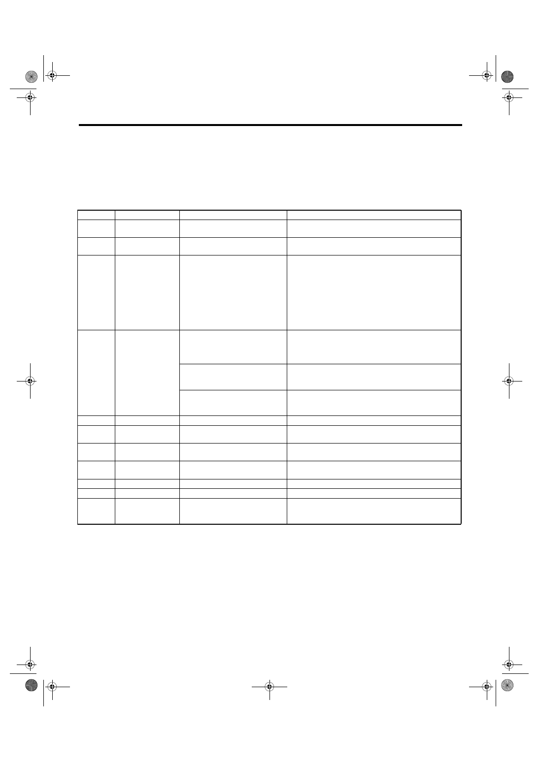
E: INSPECTION
1. BASIC INSPECTION
1) Clean all disassembled parts, and check for wear, damage or any other faults, then repair or replace as
necessary.
2) When disassembling, check the inside of gearbox for water. If any water is found, carefully check the boot
for damage, input shaft dust seal, adjusting screw and boot clips for poor sealing. If faulty, replace with new
parts.
No.
Parts
Inspection
Corrective action
1
Input shaft
(1) Bend of input shaft
(2) Damage on serration
If the bend or damage is excessive, replace the entire
gearbox.
2
Dust seal
(1) Crack or damage
(2) Wear
If the outer wall slips, the lip is worn out or damage is
found, replace it with a new one.
3
Rack and pinion
Poor mating of rack with pinion
(1) Adjust the backlash properly.
By measuring the turning torque of gearbox and sliding
resistance of rack, check if rack & pinion engage uni-
formly and smoothly with each other. (Refer to “Service
limit”.)
(2) Keeping rack pulled out all the way so that all teeth
emerge, check teeth for damage.
Even if abnormality is found in either (1) or (2), replace
the entire gearbox.
4
Gearbox unit
(1) Bend of rack shaft
(2) Bend of cylinder portion
(3) Crack or damage on cast iron
portion
Replace the gearbox with a new one.
(4) Wear or damage on rack bush
If the free play of rack shaft in radial direction is out of the
specified range, replace the gearbox with new one. (Refer
to “Service limit”.)
(5) Wear on input shaft bearing
If the free play of input shaft in radial and axial direction is
out of the specified range, replace the gearbox with a new
one. (Refer to “Service limit”.)
5
Boot
Crack, damage or deterioration
Replace.
6
Tie-rod
(1) Looseness of ball joint
(2) Bend of tie-rod
Replace.
7
Tie-rod end
Damage or deterioration on dust
seal
Replace.
8
Adjusting screw
spring
Deterioration
Replace.
9
Boot clip
Deterioration
Replace.
10
Sleeve
Damage
Replace.
11
Pipe
(1) Damage to flared surface
(2) Damage to flare nut
(3) Damage to pipe
Replace.
Нет комментариевНе стесняйтесь поделиться с нами вашим ценным мнением.
Текст