Subaru Legacy (2005 year). Service manual — part 867
AC-37
HVAC SYSTEM (HEATER, VENTILATOR AND A/C)
Heater and Cooling Unit
17.Heater and Cooling Unit
A: REMOVAL
1) Disconnect the ground cable from battery.
2) Using the refrigerant recovery system, dis-
charge refrigerant. <Ref. to AC-20, PROCEDURE,
Refrigerant Recovery Procedure.>
3) Drain coolant from the radiator.
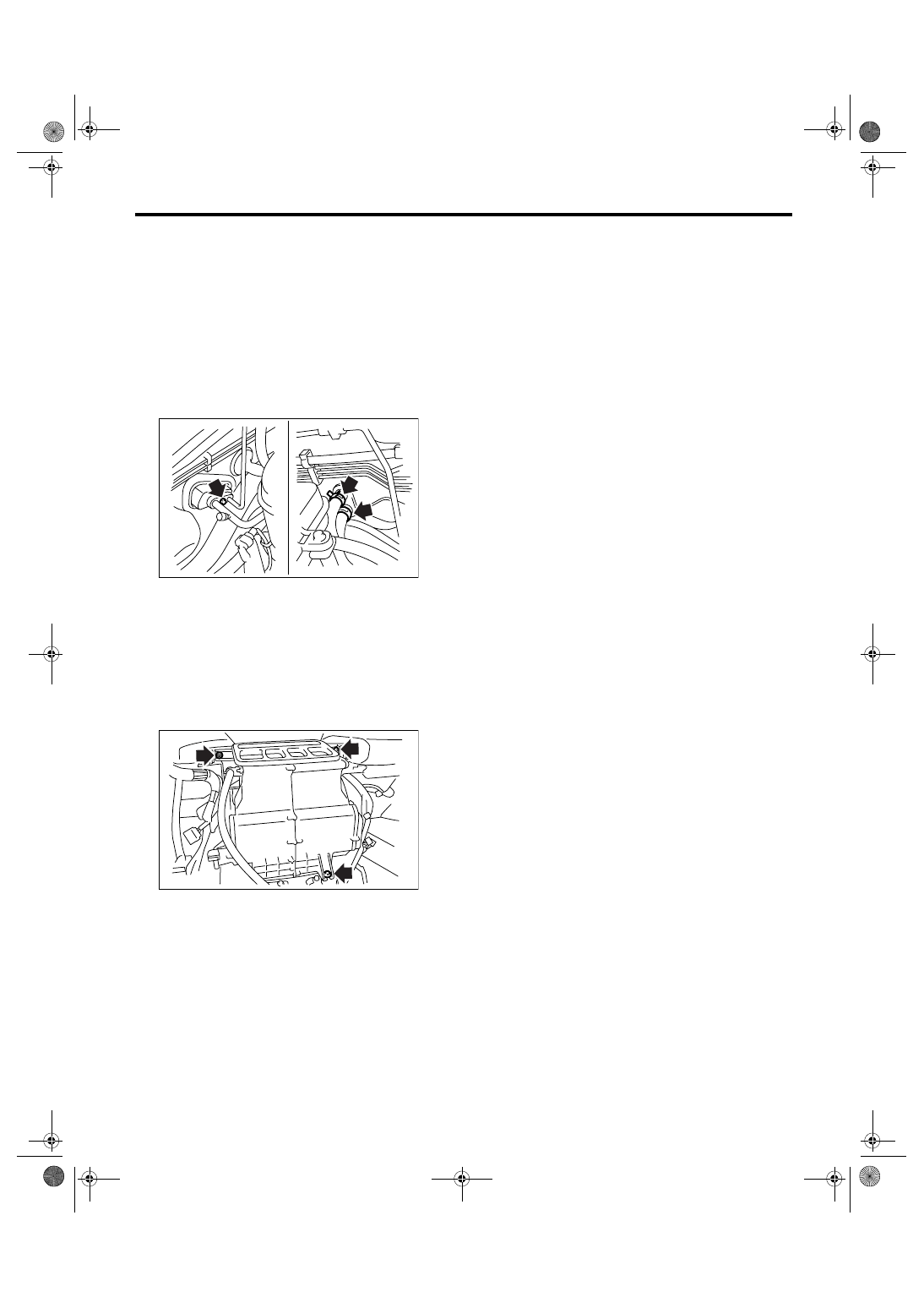
4) Remove the bolts securing expansion valve and
pipe in engine compartment. Release the heater
hose clamps in engine compartment to remove the
hoses.
5) Remove the instrument panel. <Ref. to EI-56,
REMOVAL, Instrument Panel Assembly.>
6) Remove the support beam.
7) Remove the blower motor unit assembly. <Ref.
to AC-26, REMOVAL, Blower Motor Unit Assem-
bly.>
8) Disconnect the actuator connector.
9) Remove the bolt and nuts to remove the heater
and cooling unit.
B: INSTALLATION
1) Install in the reverse order of removal.
2) Charge refrigerant. <Ref. to AC-21, PROCE-
DURE, Refrigerant Charging Procedure.>
Tightening torque:
Refer to “COMPONENT” of “General Descrip-
tion”. <Ref. to AC-5, HEATER COOLING
UNIT, COMPONENT, General Description.>
AC-00921
AC-00922
AC-38
HVAC SYSTEM (HEATER, VENTILATOR AND A/C)
Evaporator
18.Evaporator
A: REMOVAL
1) Using the refrigerant recovery system, dis-
charge refrigerant. <Ref. to AC-20, PROCEDURE,
Refrigerant Recovery Procedure.>
2) Disconnect the ground cable from battery.
3) Remove the blower motor unit assembly. <Ref.
to AC-26, REMOVAL, Blower Motor Unit Assem-
bly.>
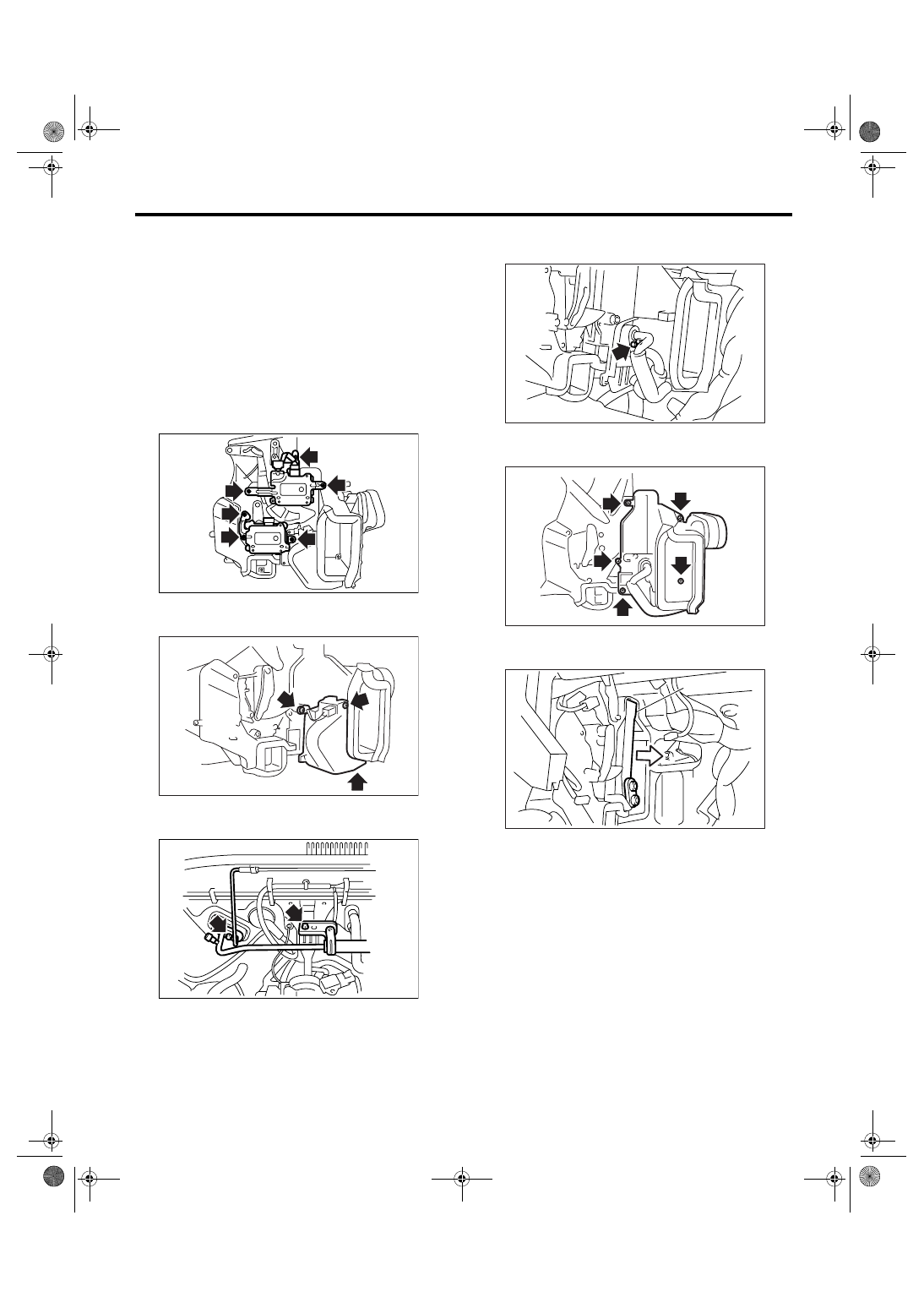
4) Disconnect the connector, remove the screw
and then remove the air-mix door actuator and
mode door actuator.
5) Disconnect the connector, remove the screw
and remove the pipe cover and evaporator sensor.
6) Remove the bolts securing expansion valve and
pipe in engine compartment.
7) Remove the bolt which holds the pipe to evapo-
rator.
8) Remove the screws and clip to remove the evap-
orator cover.
9) Pull out the evaporator (A) in the direction of ar-
row.
CAUTION:
If the evaporator is replaced, add an appropri-
ate amount of compressor oil to evaporator.
<Ref. to AC-25, REPLACEMENT, Compressor
Oil.>
B: INSTALLATION
Install in the reverse order of removal.
AC-00923
AC-00924
AC-00925
AC-00926
AC-00927
AC-00928
(A)
AC-39
HVAC SYSTEM (HEATER, VENTILATOR AND A/C)
Hose and Tube
19.Hose and Tube
A: REMOVAL
CAUTION:
• When disconnecting/connecting hoses, do
not apply an excessive force to them. Confirm
that no torsion and excessive tension is
charged after installing.
• Seal the disconnected hose with a plug or vi-
nyl tape to prevent foreign matter from enter-
ing.
1) Disconnect the ground cable from battery.
2) Using the refrigerant recovery system, dis-
charge refrigerant. <Ref. to AC-20, PROCEDURE,
Refrigerant Recovery Procedure.>
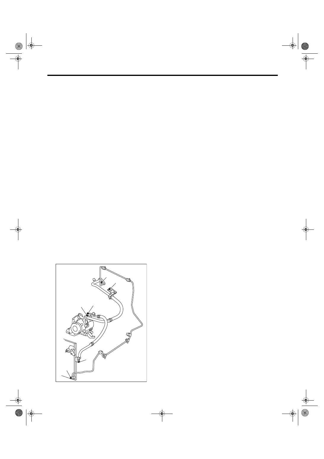
3) Remove the evaporator unit mounting bolt (A)
and low-pressure hose bracket bolt (B).
4) Remove the low-pressure hose attaching bolts
(C).
5) Disconnect the low-pressure hose from evapo-
rator unit.
6) Disconnect the low-pressure hose from com-
pressor.
7) Remove the low-pressure hose from vehicle.
8) Remove the high-pressure hose attaching bolt
(D).
9) Disconnect the high-pressure hose from com-
pressor.
10) Disconnect the high-pressure hose from con-
denser.
11) Remove the high-pressure hose from vehicle.
12) Remove the high-pressure attaching bolt (E).
13) Remove the high-pressure tube from vehicle.
B: INSTALLATION
CAUTION:
• When disconnecting or connecting the hos-
es, do not apply excessive force to them. Con-
firm that no torsion and excessive tension is
charged after installing.
• Seal the disconnected hose with a plug or vi-
nyl tape to prevent foreign matter from enter-
ing.
1) Install in the reverse order of removal.
2) Charge refrigerant. <Ref. to AC-21, PROCE-
DURE, Refrigerant Charging Procedure.>
Tightening torque:
Refer to “COMPONENT” of “General Descrip-
tion”. <Ref. to AC-10, AIR CONDITIONING
UNIT, COMPONENT, General Description.>
C: INSPECTION
Check the hoses for cracks, damage and expan-
sion. If any fault is found, replace them with new
ones.
(A)
(B)
AC-00929
(C)
(D)
(D)
(E)
AC-40
HVAC SYSTEM (HEATER, VENTILATOR AND A/C)
Relay and Fuse
20.Relay and Fuse
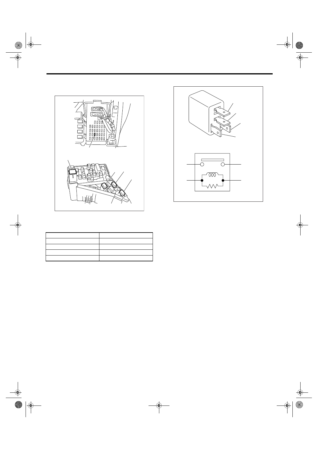
A: LOCATION
B: INSPECTION
While applying battery voltage to the terminal be-
tween (3) and (4), check continuity between (1) and
(2).
If no continuity exists, replace the relay with a new
one.
(1) Joint box
(2) Main fuse box
Main Fan Relay 1
(A)
Main Fan Relay 2
(B)
Sub Fan Relay
(C)
A/C Relay
(D)
A/C Fuse
(E)
AC-00787
(E)
(1)
(2)
(A)
(B)
(D)
(C)
(3) — (4): Continuity exists
(1) — (2): Continuity does not exist
AC-00641
(1)
(1)
(2)
(2)
(3)
(3)
(4)
(4)
Нет комментариевНе стесняйтесь поделиться с нами вашим ценным мнением.
Текст