Subaru Legacy (2005 year). Service manual — part 1046
LAN(diag)-63
LAN SYSTEM (DIAGNOSTICS)
Diagnostic Procedure with Diagnostic Trouble Code (DTC)
P: DTC B0222 CAN-HS TCM NO-RECEIVE DATA
DTC DETECTING CONDITION:
TCM has error, harness between the main harness splice and TCM is open or shorted, connectors are not
connected securely, or the terminal has poor caulking.
TROUBLE SYMPTOM:
• SPORT indicator light illuminates.
• “Er HC” is displayed in odo/trip meter.
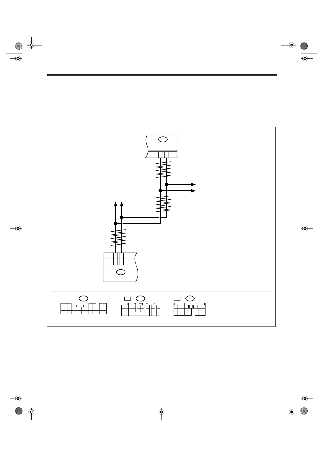
WIRING DIAGRAM:
LAN00029
B280
B:
5
4
6 7
8
2
1
9
3
10
22
23
11 12 13 14 15
24 25
26 27
16 17 18
28 29
19 20
21
30
ABSCM & H/U
VDCCM & H/U
B20
B30
BODY INTEGRATED
MODULE
B280
B:
A12
A3
TCM
B54
A:
A3
A4
5AT
4AT
ECM
B54
A:
1 2
7
8
9
5 6
3 4
10 11 12
19 20 21
13
14 15
16
17
18
22
23
24
5AT
B54
1 2
7
8 9
5
6
3
4
10 11 12
19 20 21
13 14 15 16
17 18
22 23 24
4AT A:
LAN(diag)-64
LAN SYSTEM (DIAGNOSTICS)
Diagnostic Procedure with Diagnostic Trouble Code (DTC)
Step
Check
Yes
No
1
CHECK HARNESS.
1) Disconnect the TCM connector.
2) Measure the resistance between TCM con-
nector terminals.
Connector & terminal
4AT model
(B54) No. 3 — No. 12:
5AT model
(B54) No. 3 — No. 4:
Is the resistance
∞ Ω?
Open harness in
related lines of
TCM. Repair or
replace the open
circuit of harness.
2
CHECK TCM.
Read the DTC of TCM using Subaru Select
Monitor. <Ref. to 4AT(diag)-16, READ DIAG-
NOSTIC TROUBLE CODE (DTC), OPERA-
TION, Subaru Select Monitor.> <Ref. to
5AT(diag)-17, READ DIAGNOSTIC TROUBLE
CODE (DTC), OPERATION, Subaru Select
Monitor.>
Is DTC other than “CAN com-
munication” displayed on Sub-
aru Select Monitor?
Perform the diag-
nosis according to
DTC.
Replace the TCM.
<Ref. to 4AT-66,
Transmission Con-
trol Module
(TCM).> <Ref. to
5AT-61, Transmis-
sion Control Mod-
ule (TCM).>
LAN(diag)-65
LAN SYSTEM (DIAGNOSTICS)
Diagnostic Procedure with Diagnostic Trouble Code (DTC)
Q: DTC B0223 CAN-HS VDC/ABS NO-RECEIVE DATA
DTC DETECTING CONDITION:
Defective VDC/ABSCM. (If error is in the main harness, DTC P0600 High-speed CAN circuit is input at the
same time.)
TROUBLE SYMPTOM:
• ABS warning light and VDC warning light come on.
• “Er HC” is displayed in odo/trip meter.
WIRING DIAGRAM:
Step
Check
Yes
No
1
CHECK HARNESS.
1) Disconnect the body integrated module
connector.
2) Measure the resistance between body inte-
grated module connector terminals.
Connector & terminal
(B280) No. 20 — No. 30:
Is the resistance 55 — 65
Ω?
Read the DTC of
VDC/ABSCM, and
perform the diag-
nosis according to
DTC.
LAN00152
B280
B:
5
4
6 7
8
2
1
9
3
10
22
23
11 12 13 14 15
24 25
26 27
16 17 18
28 29
19 20
21
30
VDCCM & H/U
B310
B20
B30
BODY INTEGRATED
MODULE
B280
B:
11
26
B301
ABSCM & H/U
13
29
B231
2
1
3
STEERING ANGLE
SENSOR
ABS
ABS
VDC
VDC
E
B301
4 5 6 7 8 9
16 17 18 19 20
2 3
1
21 22 23 24 25 26
10 11
13
14
12
15
B310
1 2 3 4
11 12
14 15 16 17 18 19 20 21 22 23 24 25
10
26
27 28 29 30 31 32 33 34 35 36 37 38 39 40 41 42
13
7
8
6
5
9
1 2 3 4
B231
ECM
VDC : MODEL WITH VDC
: MODEL WITHOUT VDC
ABS
LAN(diag)-66
LAN SYSTEM (DIAGNOSTICS)
Diagnostic Procedure with Diagnostic Trouble Code (DTC)
2
CHECK HARNESS.
1) Disconnect the body integrated module
connector.
2) Measure the resistance between body inte-
grated module connector terminals.
Connector & terminal
(B280) No. 20 — No. 30:
Is the resistance 115 — 125
Ω?
3
CHECK HARNESS.
1) Disconnect the body integrated module
connector.
2) Measure the resistance between body inte-
grated module connector and chassis ground.
Connector & terminal
(B280) No. 20 — Chassis ground:
(B280) No. 30 — Chassis ground:
Is the resistance
∞ Ω?
Open harness on
related line of body
integrated mod-
ule. Repair or
replace the open
circuit of harness.
4
CHECK HARNESS.
1) Disconnect the body integrated module
connector.
2) Measure the voltage between body inte-
grated module connector and chassis ground.
(Ignition switch ON)
Connector & terminal
(B280) No. 20 (+) — Chassis ground (
−
):
(B280) No. 30 (+) — Chassis ground (
−
):
Is the voltage more than 6 V?
Repair or replace
the short circuit of
harness.
5
CHECK END RESISTANCE.
1) Disconnect the VDC/ABSCM harness con-
nector.
2) Measure the resistance between VDC/
ABSCM connector terminals.
Connector & terminal
ABS
(B301) No. 11 — No. 26:
VDC
(B310) No. 13 — No. 29:
Is the resistance 115 — 125
Ω?
End resistance is
open. Replace the
VDC/ABSCM.
<Ref. to ABS-6,
ABS Control Mod-
ule and Hydraulic
Control Unit
(ABSCM&H/U).>
<Ref. to VDC-7,
VDC Control Mod-
ule and Hydraulic
Control Unit
(VDCCM&H/U).>
6
CHECK HARNESS.
1) Disconnect the body integrated module
connector and VDC/ABSCM connector.
2) Measure the resistance between body inte-
grated module connector and VDC/ABSCM
connector terminals.
Connector & terminal
ABS
(B301) No. 11 — (B280) No. 30:
(B301) No. 26 — (B280) No. 20:
VDC
(B310) No. 13 — (B280) No. 20:
(B310) No. 29 — (B280) No. 30:
Is the resistance less than 10
Ω?
Main wiring har-
ness is open.
Repair or replace
the open circuit of
harness.
7
CHECK ABS/VDC CM.
1) Connect all the connectors.
2) Read the DTC of VDC/ABSCM using Sub-
aru Select Monitor.
Is DTC other than “CAN com-
munication” displayed on Sub-
aru Select Monitor?
Perform the diag-
nosis according to
DTC concerning
VDC/ABSCM.
Temporary poor
contact occurs.
Check the con-
necting condition
of connector and
terminals.
Step
Check
Yes
No
Нет комментариевНе стесняйтесь поделиться с нами вашим ценным мнением.
Текст