Subaru Legacy (2005 year). Service manual — part 1049
LAN(diag)-75
LAN SYSTEM (DIAGNOSTICS)
Diagnostic Procedure with Diagnostic Trouble Code (DTC)
4
CHECK CURRENT DATA.
Connect the Subaru Select Monitor and dis-
play current data of the body integrated unit
(auto A/C fail).
Is OK displayed?
Perform auto A/C
self-diagnosis.
<Ref. to AC(diag)-
10, OPERATION,
Diagnostic Chart
for Self-Diagno-
sis.>
5
CHECK AUTO A/C ECM.
1) Turn the ignition switch to OFF.
2) Disconnect the auto A/C ECM connector.
3) Turn the ignition switch to ON.
Does B0302 disappear?
6
CHECK HARNESS.
1) Disconnect the body integrated unit con-
nector (B280) and auto A/C control module
connector (B283).
2) Check for open and short circuits between
body integrated unit connector and auto A/C
control module connector.
Connector & terminal
(B283) No. 1 — (B280) No. 26:
(B283) No. 11— (B280) No. 25:
Is the harness in normal condi-
tion?
Replace the auto
A/C ECM. <Ref. to
AC-33, REMOVAL,
Control Unit (Auto
A/C Model).>
Repair or replace
the open or short
circuit of harness.
7
CHECK CURRENT DATA.
Connect the Subaru Select Monitor and dis-
play current data of the body integrated unit
(meter fail).
Is OK displayed?
Replace the com-
bination meter.
<Ref. to IDI-15,
REMOVAL, Com-
bination Meter.>
8
CHECK COMBINATION METER.
1) Turn the ignition switch to OFF.
2) Disconnect the combination meter connec-
tor.
3) Turn the ignition switch to ON.
Is B0302 detected?
Replace the com-
bination meter.
<Ref. to IDI-15,
REMOVAL, Com-
bination Meter.>
9
CHECK HARNESS.
1) Disconnect the combination meter connec-
tor (i10).
2) Check for open and short circuits between
the body integrated unit and combination
meter connectors.
Connector & terminal
(i10) No. 21 — (i84) No. 27:
(i10) No. 22 — (i84) No. 26:
Is the harness in normal condi-
tion?
Repair or replace
the open or short
circuit of harness.
10
CHECK CURRENT DATA.
Check the current data of the body integrated
unit (center display fail).
Is OK displayed?
Repair or replace
the center display.
<Ref. to ET-15,
REMOVAL, Navi-
gation Display.>
11
CHECK CENTER DISPLAY.
1) Turn the ignition switch to OFF.
2) Disconnect the center display connector
(i90 or i92).
3) Turn the ignition switch to ON.
Does B0302 disappear?
Step
Check
Yes
No
LAN(diag)-76
LAN SYSTEM (DIAGNOSTICS)
Diagnostic Procedure with Diagnostic Trouble Code (DTC)
12
CHECK HARNESS.
1) Disconnect the body integrated unit con-
nector (B280) and the center display connector
(i90 or i92).
2) Check for open and short circuits between
the body integrated unit connector and the
center display connector.
Connector & terminal
Model with navigation
(i90) No. 6 — (i84) No. 26:
(i90) No. 14 — (i84) No. 27:
Model without navigation
(i92) No. 2 — (i84) No. 26:
(i92) No. 4 — (i84) No. 27:
Is the harness in normal condi-
tion?
Replace the center
display. <Ref. to
ET-15, REMOVAL,
Navigation Dis-
play.>
Repair or replace
the open or short
circuit of harness.
13
CHECK COMBINATION METER.
1) Display the current data of body integrated
unit using Subaru Select Monitor.
2) Display the door switch in analog data.
3) Read the display of data and combination
meter when each door is opened/closed.
Do the body integrated unit
data indicator and combina-
tion meter indicator change
according to operation?
14
CHECK AUTO A/C CONTROL MODULE
HARNESS.
1) Disconnect the auto A/C control module
connector.
2) Disconnect the body integrated unit con-
nector.
3) Measure the resistance between the body
integrated unit and auto A/C control module
harness.
Connector & terminal
(B280) No. 26 — (B283) No. 1:
(B280) No. 25 — (B283) No. 11:
Is the resistance less than
10
Ω?
Repair the open
circuit of harness
or replace har-
ness.
15
CHECK COMBINATION METER HARNESS.
1) Disconnect the combination meter connec-
tor.
2) Disconnect the body integrated unit con-
nector.
3) Measure the resistance between the body
integrated unit and combination meter connec-
tor.
Connector & terminal
(i84) No. 27 — (i10) No. 21:
(i84) No. 26 — (i10) No. 22:
Is the resistance less than
10
Ω?
Repair the open
circuit of harness
or replace har-
ness.
16
CHECK AUTO A/C CONTROL MODULE.
Perform auto A/C control module self-diagno-
sis. <Ref. to AC(diag)-13, A/C CONTROL
SYSTEM SELF-DIAGNOSIS, OPERATION,
Diagnostic Chart for Self-Diagnosis.>
Is the self-diagnosis OK?
Replace the auto
A/C control mod-
ule. <Ref. to AC-
33, REMOVAL,
Control Unit (Auto
A/C Model).>
17
CHECK COMBINATION METER.
Perform self-diagnosis for the combination
meter system. <Ref. to IDI-3, SELF-DIAGNO-
SIS, INSPECTION, Combination Meter Sys-
tem.>
Is the self-diagnosis OK?
Replace the body
integrated unit.
<Ref. to SL-44,
REMOVAL, Body
Integrated Mod-
ule.>
Replace the com-
bination meter.
<Ref. to IDI-15,
REMOVAL, Com-
bination Meter.>
Step
Check
Yes
No
LAN(diag)-77
LAN SYSTEM (DIAGNOSTICS)
Diagnostic Procedure with Diagnostic Trouble Code (DTC)
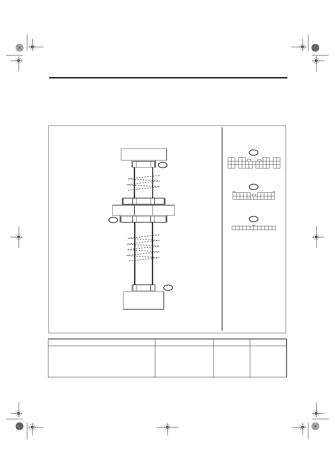
U: DTC B0311 CAN-LS METER UNIT DATA ABNORMAL
DTC DETECTING CONDITION:
Combination meter error, or harness between the main harness splice and combination meter is open or
shorted, the connector is not connected securely and the terminal has poor caulking.
TROUBLE SYMPTOM:
“Er Lc” is displayed in odo/trip meter.
WIRING DIAGRAM:
Step
Check
Yes
No
1
CHECK COMBINATION METER.
Perform the self-diagnosis for combination
meter. <Ref. to IDI-3, SELF-DIAGNOSIS,
INSPECTION, Combination Meter System.>
Is the self-diagnosis OK?
Read the DTC
again, and then
perform the diag-
nosis according to
DTC displayed on
the top.
Replace the com-
bination meter.
<Ref. to IDI-15,
Combination
Meter.>
i77
2
8
7
1
i10
21
22
i84
27
26
LAN00176
1 2
3 4
5 6
7 8
9 10 11 12 13 14 15 16 17 18 19 20 21 22 23
24 25
26 27 28 29
30 31 32 33
34 35
2 3 4 5
6 7 8 9
12 13 14 15 16 17 18 19 20 21 22
10
1
11
i84
CAN JOINT
CONNECTOR
TWISTED WIRE
i10
COMBINATION METER
BODY INTEGRATED
MODULE
i77
1 2 3 4 5 6 7 8 9 10 11 12
LAN(diag)-78
LAN SYSTEM (DIAGNOSTICS)
Diagnostic Procedure with Diagnostic Trouble Code (DTC)
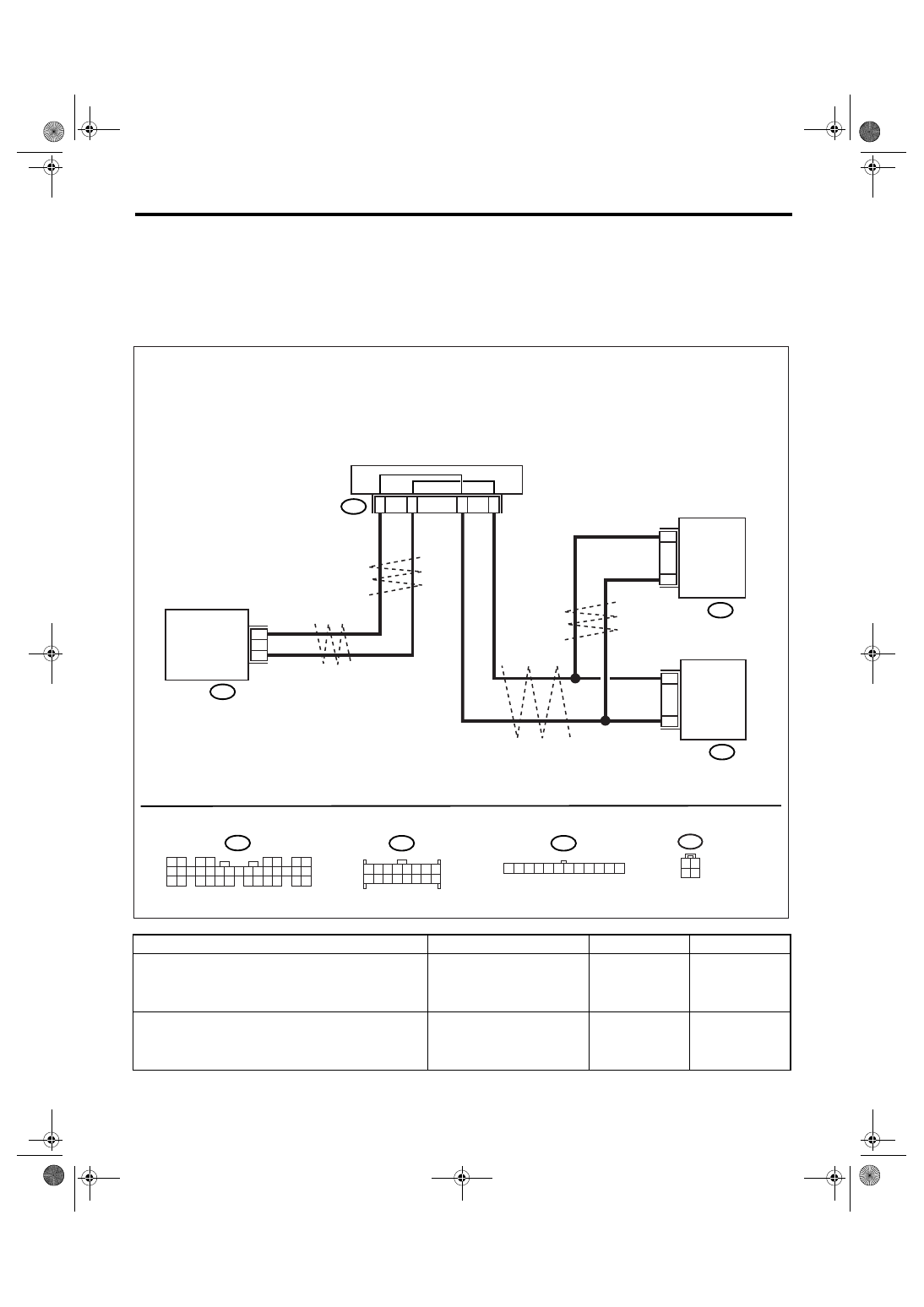
V: DTC B0313 CAN-LS MONITOR DATA ABNORMAL
DTC DETECTING CONDITION:
Center display unit error, or harness between the main harness splice and center display unit is open or
shorted, the connector is not connected securely and the terminal has poor caulking.
TROUBLE SYMPTOM:
“Er LC” is displayed in odo/trip meter.
WIRING DIAGRAM:
Step
Check
Yes
No
1
CHECK CENTER DISPLAY.
1) Display the current data of body integrated
module using Subaru Select Monitor.
2) Read the fail display of center display.
Is the center display fail OK?
Replace the center
display.
2
CHECK NAVIGATION.
1) Display the current data of body integrated
module using Subaru Select Monitor.
2) Read the display of NAVI fail.
Is the NAVI fail OK?
Replace the center
display.
Repair the naviga-
tion module.
i77
2
5
8
11
14
6
i90
27
26
i84
LAN00177
i84
1 2
3 4
5 6
7 8
9 10 11 12 13 14 15 16 17 18 19 20 21 22 23
24 25
26 27 28 29
30 31 32 33
34 35
i90
5 6 7
8
2
1
4
3
11
10
12 13 14 15
8
16
CAN JOINT CONNECTOR
MODEL WITHOUT
NAVIGATION SYSTEM
BODY
INTEGRATED
MODULE
CENTER
DISPLAY
TWISTED WIRE
i77
1 2 3 4 5 6 7 8 9 10 11 12
4
2
i103
CENTER
DISPLAY
MODEL WITH
NAVIGATION SYSTEM
i103
1 2
3 4
Нет комментариевНе стесняйтесь поделиться с нами вашим ценным мнением.
Текст