Subaru Legacy (2005 year). Service manual — part 214
EN(H4SO 2.5)(diag)-141
ENGINE (DIAGNOSTICS)
Diagnostic Procedure with Diagnostic Trouble Code (DTC)
Step
Check
Yes
No
1
CHECK OPTION CODE.
Is the option code EC, EK, EH,
ER or K4?
Refer to EN(H4SO
2.0) section. <Ref.
to EN(H4SO
2.0)(diag)-64, List
of Diagnostic Trou-
ble Code (DTC).>
NOTE:
Fuel injection sys-
tem for KA and KS
model is the same
as 2.0 L model.
2
CHECK SENSOR OUTPUT.
1) Turn the ignition switch to ON.
2) Read the data of sub throttle sensor signal
using Subaru Select Monitor.
NOTE:
For detailed operation procedure, refer to
“READ CURRENT DATA FOR ENGINE”. <Ref.
to EN(H4SO 2.5)(diag)-25, Subaru Select Mon-
itor.>
Is the voltage less than 4.73
V?
3
CHECK POOR CONTACT.
Check poor contact in connector between
ECM and electronic throttle control.
Is there poor contact in con-
nector between ECM and elec-
tronic throttle control?
Repair the poor
contact.
Temporary poor
contact occurred,
but it is normal at
present.
4
CHECK HARNESS BETWEEN ECM AND
ELECTRONIC THROTTLE CONTROL.
1) Turn the ignition switch to OFF.
2) Disconnect the connector from ECM.
3) Disconnect the connectors from electronic
throttle control.
4) Measure the resistance between ECM con-
nector and electronic throttle control connector.
Connector & terminal
(B136) No. 35 — (E57) No. 3:
(B136) No. 29 — (E57) No. 4:
Is the resistance less than 1
Ω?
Repair the open
circuit of harness
connector.
5
CHECK HARNESS BETWEEN ECM AND
ELECTRONIC THROTTLE CONTROL.
1) Connect the ECM connector.
2) Measure the resistance between electronic
throttle control connector and engine ground.
Connector & terminal
(E57) No. 3 — Engine ground:
Is the resistance less than 5
Ω?
Repair the poor
contact in ECM
connector.
Replace the ECM
if defective. <Ref.
to FU(H4SO 2.5)-
37, Engine Con-
trol Module
(ECM).>
6
CHECK HARNESS BETWEEN ECM AND
ELECTRONIC THROTTLE CONTROL.
Measure the voltage between electronic throt-
tle control connector and engine ground.
Connector & terminal
(E57) No. 4 (+) — Engine ground (
−
):
Is the voltage less than 10 V?
Repair the battery
short circuit of har-
ness between
ECM connector
and electronic
throttle control
connector.
7
CHECK HARNESS BETWEEN ECM AND
ELECTRONIC THROTTLE CONTROL.
1) Turn the ignition switch to OFF.
2) Disconnect the connector from ECM.
3) Measure the resistance between connector
terminals.
Connector & terminal
(B136) No. 29 — (B136) No. 16:
Is the resistance more than 1
M
Ω?
Repair the poor
contact. Replace
the electronic
throttle control.
Sensor power sup-
ply circuit may be
shorted.
EN(H4SO 2.5)(diag)-142
ENGINE (DIAGNOSTICS)
Diagnostic Procedure with Diagnostic Trouble Code (DTC)
AB:DTC P0301 CYLINDER 1 MISFIRE DETECTED
NOTE:
For the diagnostic procedure, refer to DTC P0304. <Ref. to EN(H4SO 2.5)(diag)-143, DTC P0304 CYLIN-
DER 4 MISFIRE DETECTED, Diagnostic Procedure with Diagnostic Trouble Code (DTC).>
AC:DTC P0302 CYLINDER 2 MISFIRE DETECTED
NOTE:
For the diagnostic procedure, refer to DTC P0304. <Ref. to EN(H4SO 2.5)(diag)-143, DTC P0304 CYLIN-
DER 4 MISFIRE DETECTED, Diagnostic Procedure with Diagnostic Trouble Code (DTC).>
AD:DTC P0303 CYLINDER 3 MISFIRE DETECTED
NOTE:
For the diagnostic procedure, refer to DTC P0304. <Ref. to EN(H4SO 2.5)(diag)-143, DTC P0304 CYLIN-
DER 4 MISFIRE DETECTED, Diagnostic Procedure with Diagnostic Trouble Code (DTC).>
EN(H4SO 2.5)(diag)-143
ENGINE (DIAGNOSTICS)
Diagnostic Procedure with Diagnostic Trouble Code (DTC)
AE:DTC P0304 CYLINDER 4 MISFIRE DETECTED
DTC DETECTING CONDITION:
• Detects when malfunction occurs in 2 continuous driving cycles.
• Immediately at fault recognition (A misfire which could damage catalyst occurs.)
TROUBLE SYMPTOM:
• Engine stalls.
• Erroneous idling
• Rough driving
CAUTION:
After repair or replacement of faulty parts, conduct Clear Memory Mode <Ref. to EN(H4SO 2.5)(diag)-
40, Clear Memory Mode.> and Inspection Mode <Ref. to EN(H4SO 2.5)(diag)-33, Inspection Mode.>.
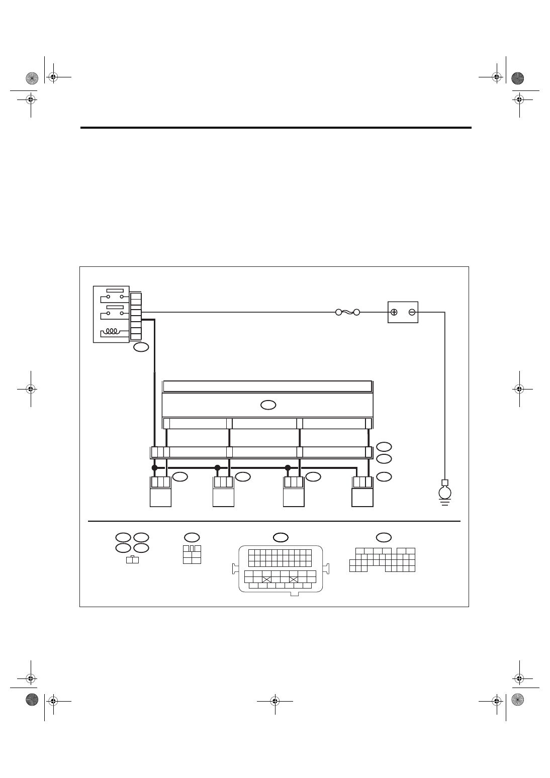
WIRING DIAGRAM:
• EC, EK, EH, ER and K4 model
• KA and KS model
NOTE:
Fuel injection system for KA and KS model is the same as 2.0 L model. Refer to EN(H4SO 2.0) section.
EN-03456
E6
E17
E5
E16
1 2
1
2
1
2
1
2
1
2
4
5
6
3
42
48
43
44
45
ECM
B136
E5
E16
E6
E17
B21
E2
FUEL INJECTOR
No. 1
FUEL INJECTOR
No. 2
FUEL INJECTOR
No. 3
FUEL INJECTOR
No. 4
BATTERY
SBF-7
B47
MAIN RELAY
1
2
6
3
5
B47
3
4
1
2
5
6
E
B136
5
6
7 8
2
1
9
4
3
10
24
22 23
25
11 12 13 14 15
26 27
28
16
17 18 19 20 21
33 34
29
32
30
31
35
B21
1 2 3 4
12 13 14 15
5 6 7 8
16 17 18 19
9 10 11
20 21 22
23 24 25 26 27 28 29 30 31 32 33
35
34
37
36
39
38
41
40
43
42
44
45
47
46
49
48
51
50
53
52
54
4
EN(H4SO 2.5)(diag)-144
ENGINE (DIAGNOSTICS)
Diagnostic Procedure with Diagnostic Trouble Code (DTC)
Step
Check
Yes
No
1
CHECK OPTION CODE.
Is the option code EC, EK, EH,
ER or K4?
Refer to EN(H4SO
2.0) section. <Ref.
to EN(H4SO
2.0)(diag)-64, List
of Diagnostic Trou-
ble Code (DTC).>
NOTE:
Fuel injection sys-
tem for KA and KS
model is the same
as 2.0 L model.
2
CHECK ANY OTHER DTC ON DISPLAY.
Is any other DTC displayed?
Inspect the rele-
vant DTC using
“List of Diagnostic
Trouble Code
(DTC)”. <Ref. to
EN(H4SO
2.5)(diag)-69, List
of Diagnostic Trou-
ble Code (DTC).>
3
CHECK OUTPUT SIGNAL FROM ECM.
1) Turn the ignition switch to ON.
2) Measure the voltage between ECM con-
nector and chassis ground on faulty cylinders.
Connector & terminal
#1 (B136) No. 6 (+) — Chassis ground (
−
):
#2 (B136) No. 5 (+) — Chassis ground (
−
):
#3 (B136) No. 4 (+) — Chassis ground (
−
):
#4 (B136) No. 3 (+) — Chassis ground (
−
):
Is the voltage more than 10 V? Go to step 8.
4
CHECK HARNESS BETWEEN FUEL INJEC-
TOR AND ECM CONNECTOR.
1) Turn the ignition switch to OFF.
2) Disconnect the connector from fuel injector
on faulty cylinders.
3) Disconnect the connector from ECM.
4) Measure the resistance between ECM con-
nector and engine ground on faulty cylinders.
Connector & terminal
#1 (E5) No. 1 — Engine ground:
#2 (E16) No. 1 — Engine ground:
#3 (E6) No. 1 — Engine ground:
#4 (E17) No. 1 — Engine ground:
Is the resistance more than 1
M
Ω?
Repair the ground
short circuit of har-
ness between fuel
injector and ECM
connector.
5
CHECK HARNESS BETWEEN FUEL INJEC-
TOR AND ECM CONNECTOR.
Measure the resistance of harness connector
between ECM connector and fuel injector on
faulty cylinders.
Connector & terminal
#1 (B136) No. 6 — (E5) No. 1:
#2 (B136) No. 5 — (E16) No. 1:
#3 (B136) No. 4 — (E6) No. 1:
#4 (B136) No. 3 — (E17) No. 1:
Is the resistance less than 1
Ω?
Repair the har-
ness and connec-
tor.
NOTE:
In this case, repair
the following:
• Open circuit of
harness between
ECM and fuel
injector connector
• Poor contact in
coupling connector
6
CHECK FUEL INJECTOR.
Measure the resistance between fuel injector
terminals on faulty cylinder.
Terminals
No. 1 — No. 2:
Is the resistance 5 — 20
Ω?
Replace the faulty
fuel injector. <Ref.
to FU(H4SO 2.5)-
32, Fuel Injector.>
Нет комментариевНе стесняйтесь поделиться с нами вашим ценным мнением.
Текст