Subaru Legacy (2005 year). Service manual — part 519
4AT-57
AUTOMATIC TRANSMISSION
Front Vehicle Speed Sensor
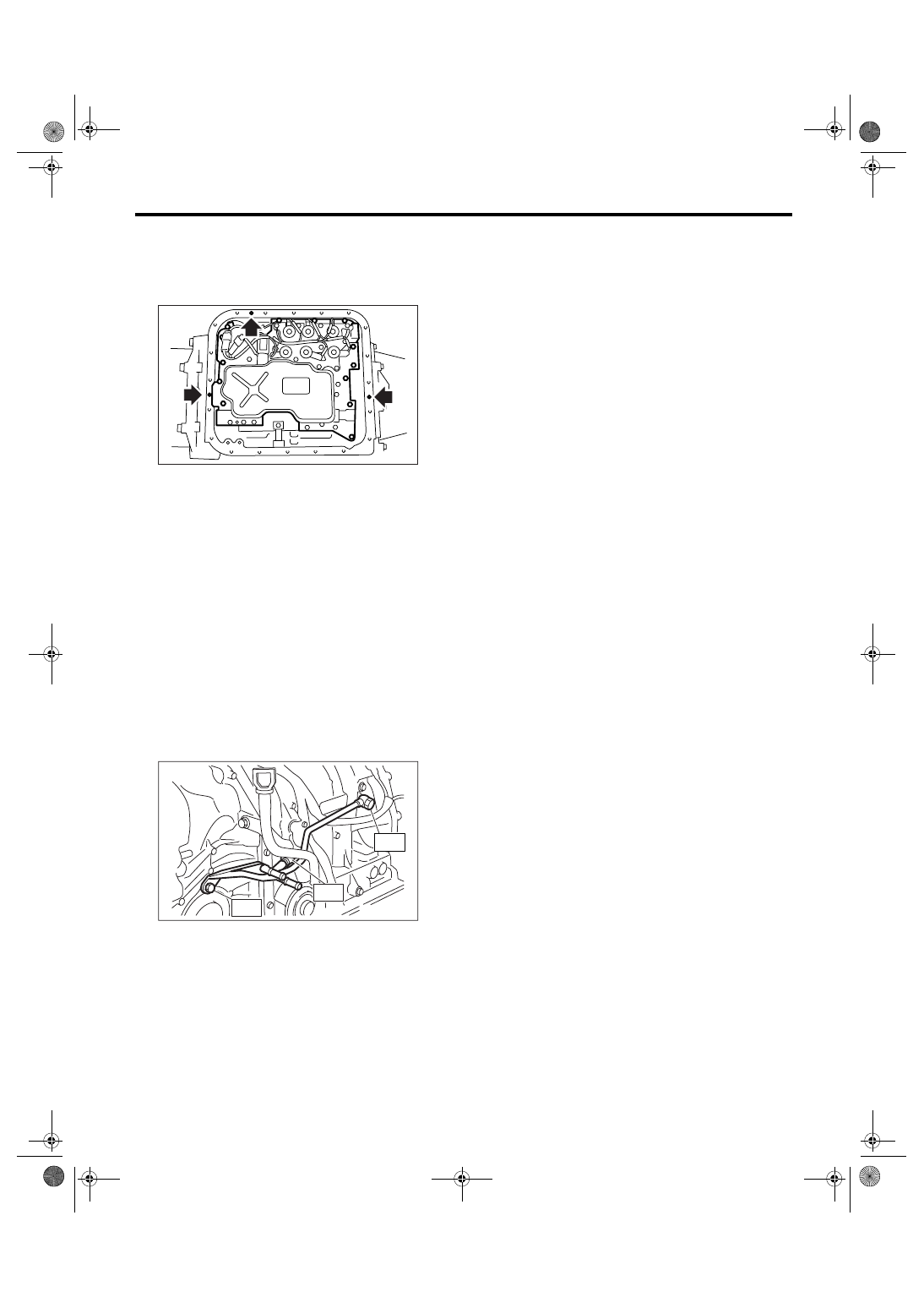
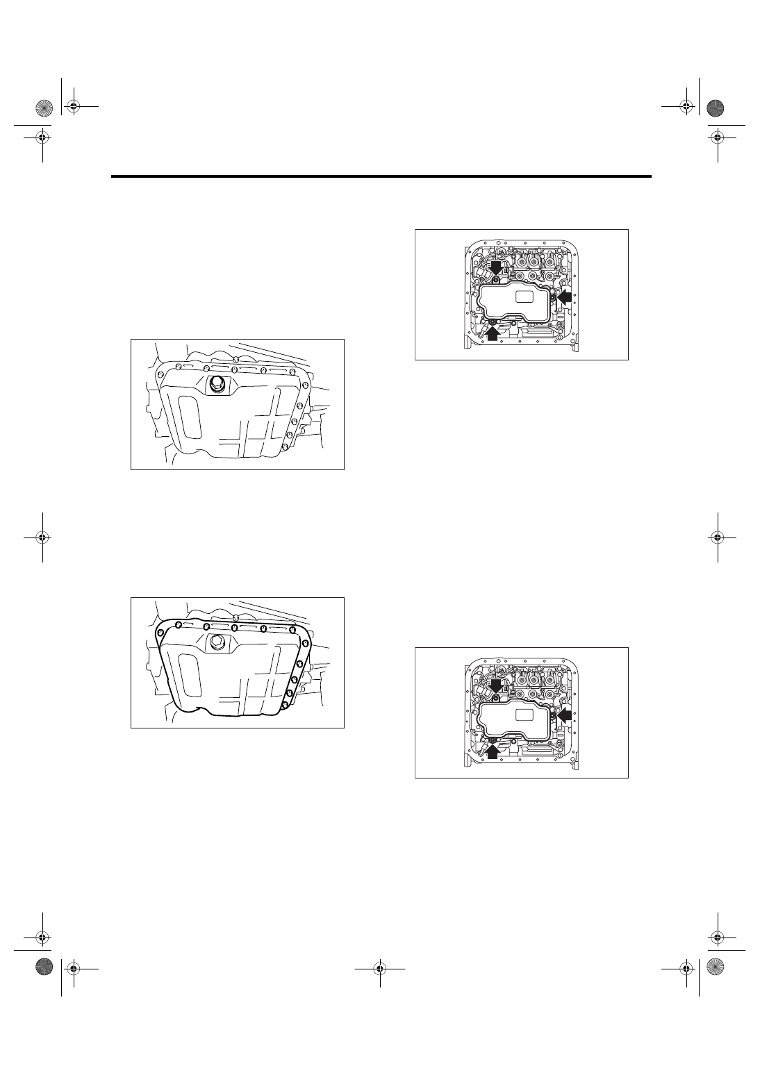
4) Apply liquid gasket fully to the three holes other
than screw holes on the transmission case.
Liquid gasket:
THREE BOND 1217B (Part No. K0877YA020)
5) Install the oil pan.
Tightening torque:
5 N
⋅
m (0.5 kgf-m, 3.6 ft-lb)
6) Install the front vehicle speed sensor and torque
converter turbine speed sensor.
Tightening torque:
7 N
⋅
m (0.7 kgf-m, 5.1 ft-lb)
7) Connect the connector to rear vehicle speed
sensor.
8) Install the oil cooler pipe.
NOTE:
Use a new copper washer.
Tightening torque:
T1: 25 N
⋅
m (2.5 kgf-m, 18.4 ft-lb)
T2: 40 N
⋅
m (4.1 kgf-m, 29.5 ft-lb)
T3: 44 N
⋅
m (4.5 kgf-m, 32.5 ft-lb)
9) Install the transmission rear crossmember bolt.
Tightening torque:
70 N
⋅
m (7.1 kgf-m, 51.6 ft-lb)
10) Install the propeller shaft. <Ref. to DS-11, IN-
STALLATION, Propeller Shaft.>
11) Install the heat shield cover.
12) Install the front, center and rear exhaust pipes
and muffler.
<Ref. to EX(H4SO 2.0)-7, INSTALLATION, Front
Exhaust Pipe.> <Ref. to EX(H4SO 2.0)-10, IN-
STALLATION, Rear Exhaust Pipe.> <Ref. to
EX(H4SO 2.0)-12, INSTALLATION, Muffler.>
13) Lower the vehicle.
14) Install the transmission connector to the stay.
15) Install the pitching stopper. <Ref. to 4AT-47,
INSTALLATION, Transmission Mounting System.>
16) Install the air intake chamber.
<Ref. to IN(H4SO 2.0)-7, INSTALLATION, Air In-
take Chamber.>
17) Fill the same amount of ATF when drained.
18) Bleed the air of control valve.
<Ref. to 4AT-64, Air Bleeding of Control Valve.>
19) Check the level of ATF. <Ref. to 4AT-31, Auto-
matic Transmission Fluid.>
20) Execute the learning control promotion. <Ref.
to 4AT(diag)-18, FACILITATION OF LEARNING
CONTROL, OPERATION, Subaru Select Moni-
tor.>
AT-01339
AT-03072
T2
T3
T1
4AT-58
AUTOMATIC TRANSMISSION
Rear Vehicle Speed Sensor
15.Rear Vehicle Speed Sensor
A: REMOVAL
1) Set the vehicle on a lift, and then lift up the vehi-
cle.
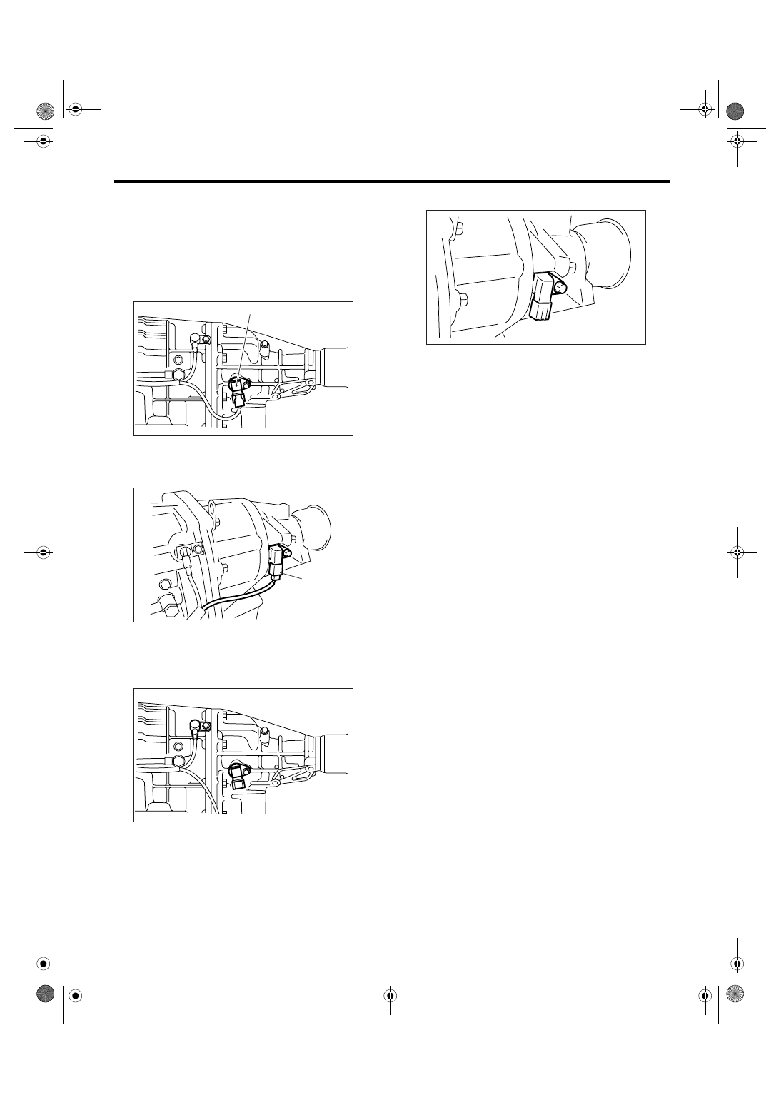
2) Disconnect the connector from rear vehicle
speed sensor.
• MP-T model
• VTD model
3) Remove the rear vehicle speed sensor.
• MP-T model
• VTD model
B: INSTALLATION
Install in the reverse order of removal.
NOTE:
Replace O-ring with a new one.
Tightening torque:
7 N
⋅
m (0.7 kgf-m, 5.1 ft-lb)
(A) Rear vehicle speed sensor
(A) Rear vehicle speed sensor
AT-02207
(A)
AT-00117
(A)
AT-01341
AT-00309
4AT-59
AUTOMATIC TRANSMISSION
Torque Converter Turbine Speed Sensor
16.Torque Converter Turbine
Speed Sensor
A: REMOVAL
For removal procedure of torque converter turbine
speed sensor, refer to “Front Vehicle Speed Sen-
sor”. <Ref. to 4AT-55, REMOVAL, Front Vehicle
Speed Sensor.>
B: INSTALLATION
For installation procedure of torque converter tur-
bine speed sensor, refer to “Front Vehicle Speed
Sensor”. <Ref. to 4AT-56, INSTALLATION, Front
Vehicle Speed Sensor.>
4AT-60
AUTOMATIC TRANSMISSION
Control Valve Strainer
17.Control Valve Strainer
A: REMOVAL
1) Set the vehicle on a lift.
2) Disconnect the ground cable from the battery.
3) Lift up the vehicle.
4) Clean the transmission exterior.
5) Remove the drain plug (ATF) to drain the ATF.
CAUTION:
The ATF will be extremely hot after driving. Be
careful not to receive burns.
6) Perform replacement with a new gasket, and
tighten the drain plug (ATF).
Tightening torque:
25 N
⋅
m (2.5 kgf-m, 18.4 ft-lb)
7) Remove the oil pan.
CAUTION:
Be careful not to allow foreign matter such as
dust or dirt to enter the oil pan.
8) Remove the magnet.
9) Clean the magnet.
10) Completely remove the remaining liquid gasket
on the transmission case and oil pan.
11) Remove the control valve strainer tightening
bolt, and remove control valve strainer from the
control valve body.
B: INSTALLATION
1) Check the control valve body for dust and other
foreign matter.
2) Mount new control valve strainer to the control
valve body.
(1) Apply ATF to the entire perimeter of the O-
ring on the control valve strainer.
CAUTION:
Protect the O-ring from dust and dirt while ap-
plying ATF.
(2) Install the control valve strainer to the con-
trol valve body from the O-ring side.
CAUTION:
If the control valve strainer is pushed in at an
angle, the O-ring may be damaged. Be sure to
push in the control valve strainer straight to in-
stall.
(3) Tighten the three bolts.
Tightening torque:
10 N
⋅
m (1.0 kgf-m, 7.4 ft-lb)
AT-03117
AT-03118
AT-04597
AT-04597
Нет комментариевНе стесняйтесь поделиться с нами вашим ценным мнением.
Текст