Subaru Legacy (2005 year). Service manual — part 548
4AT(diag)-29
AUTOMATIC TRANSMISSION (DIAGNOSTICS)
Diagnostic Procedure for Subaru Select Monitor Communication
10
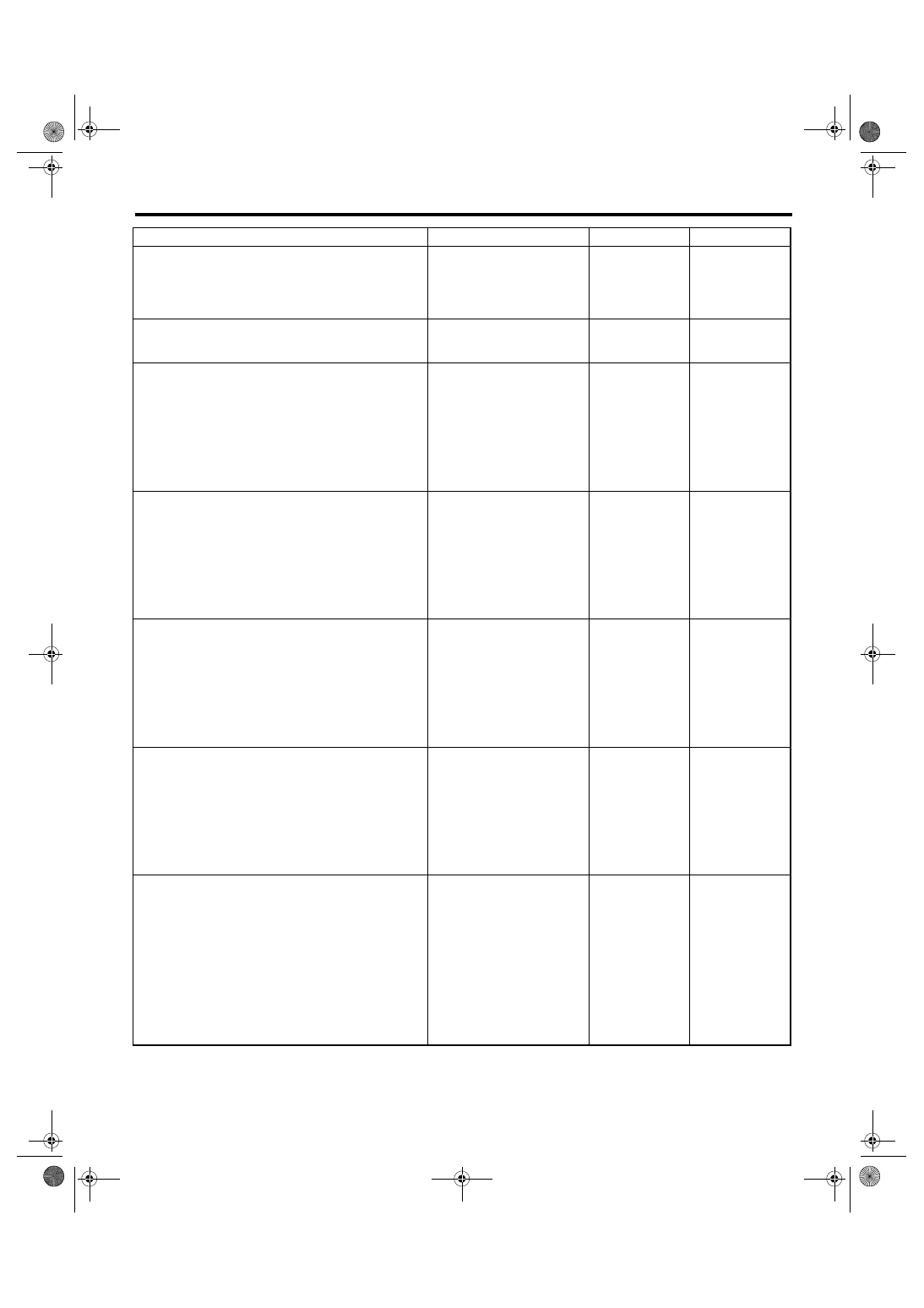
CHECK INSTALLATION OF TRANSMISSION
HARNESS CONNECTOR.
Is the transmission harness
connector connected to bulk-
head harness connector?
Connect the bulk-
head harness con-
nector to
transmission har-
ness connector.
11
CHECK POOR CONTACT IN CONNECTORS. Is there poor contact in control
module power supply and data
link connector?
Repair the poor
contact.
12
CHECK POWER SUPPLY OF TCM.
1) Disconnect the connector from TCM.
2) Turn the ignition switch to ON.
3) Measure the voltage between TCM con-
nector and chassis ground.
Connector & terminal
(B55) No. 27 (+) — Chassis ground (
−
):
(B55) No. 28 (+) — Chassis ground (
−
):
(B55) No. 29 (+) — Chassis ground (
−
):
Is the voltage 10 — 13 V?
13
CHECK FUSE.
1) Turn the ignition switch to OFF.
2) Remove the fuse M/B (No. 12).
Is the fuse M/B (No. 12) blown
out?
Replace the fuse
M/B (No. 12). If the
replaced fuse M/B
(No. 12) has blown
out easily, repair
the short circuit of
harness between
fuse M/B (No. 12)
and TCM.
Repair the open
circuit of harness
between fuse M/B
(No. 12) and TCM,
or fuse M/B (No.
12) and battery,
and poor contact
in connector.
14
CHECK IGNITION POWER SUPPLY CIR-
CUIT.
1) Turn the ignition switch to ON (engine
OFF).
2) Measure the ignition power supply voltage
between TCM connector and chassis ground.
Connector & terminal
(B55) No. 21 (+) — Chassis ground (
−
):
(B55) No. 31 (+) — Chassis ground (
−
):
Is the voltage 10 — 13 V?
15
CHECK FUSE.
Remove the fuse F/B (No. 12).
Is the fuse F/B (No. 12) blown
out?
Replace the fuse
F/B (No. 12). If the
replaced fuse F/B
(No. 12) has blown
out easily, repair
the short circuit of
harness between
fuse F/B (No. 12)
and TCM.
Repair the open
circuit of harness
between fuse F/B
(No. 12) and TCM,
or fuse F/B (No.
12) and battery,
and poor contact
in connector.
16
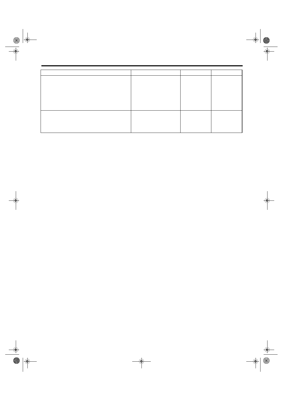
CHECK HARNESS CONNECTOR BETWEEN
TCM AND TRANSMISSION.
1) Turn the ignition switch to OFF.
2) Disconnect the connectors from TCM and
transmission.
3) Measure the resistance of harness
between TCM and transmission connector.
Connector & terminal
(B54) No. 8 — (B11) No. 19:
(B54) No. 17 — (B11) No. 19:
(B55) No. 2 — (B11) No. 20:
(B55) No. 3 — (B11) No. 20:
Is the resistance less than 1
Ω?
Repair the open
circuit of harness
between TCM and
transmission har-
ness connector,
and poor contact
in connector.
Step
Check
Yes
No
4AT(diag)-30
AUTOMATIC TRANSMISSION (DIAGNOSTICS)
Diagnostic Procedure for Subaru Select Monitor Communication
17
CHECK HARNESS CONNECTOR BETWEEN
TRANSMISSION AND TRANSMISSION
GROUND.
Measure the resistance of harness between
transmission and transmission ground.
Connector & terminal
(T4) No. 19 — Transmission ground:
(T4) No. 20 — Transmission ground:
Is the resistance less than 1
Ω?
Repair the open
circuit of harness
between transmis-
sion and transmis-
sion ground.
18
CHECK POOR CONTACT IN CONNECTORS. Is there poor contact in TCM
power supply, ground and data
link connector?
Repair the con-
nector.
Replace the TCM.
<Ref. to 4AT-66,
Transmission Con-
trol Module
(TCM).>
Step
Check
Yes
No
4AT(diag)-31
AUTOMATIC TRANSMISSION (DIAGNOSTICS)
List of Diagnostic Trouble Code (DTC)
12.List of Diagnostic Trouble Code (DTC)
A: LIST
DTC
Item
Contents of diagnosis
Reference target
P0705
Transmission Range
Sensor Circuit (PRNDL
Input)
Inhibitor switch malfunction short
circuit
P0712
Transmission Fluid Tem-
perature Sensor Circuit
Low Input
ATF temperature sensor is faulty
or input signal circuit is open.
P0713
Transmission Fluid Tem-
perature Sensor Circuit
High Input
ATF temperature sensor is faulty
or input signal circuit is shorted.
P0715
Input/Turbine Speed
Sensor Circuit
Torque converter turbine speed
sensor malfunction, short input
signal circuit
P0719
Torque Converter/Brake
Switch “B” Circuit Low
Brake switch malfunction, open
input signal circuit
P0720
Output Speed Sensor
Circuit
Front vehicle speed sensor mal-
function, open or short input sig-
nal circuit
P0724
Torque Converter/Brake
Switch “B” Circuit High
Brake switch malfunction, short
input signal circuit
P0725
Engine Speed Input Cir-
cuit
Open or short engine speed out-
put signal circuit
P0731
Gear 1 Incorrect Ratio
Vehicle sensor, torque converter
turbine speed sensor or control
valve malfunction
P0732
Gear 2 Incorrect Ratio
Vehicle sensor, torque converter
turbine speed sensor or control
valve malfunction
P0733
Gear 3 Incorrect Ratio
Vehicle sensor, torque converter
turbine speed sensor or control
valve malfunction
P0734
Gear 4 Incorrect Ratio
Vehicle sensor, torque converter
turbine speed sensor or control
valve malfunction
P0736
Reverse Incorrect Ratio
Vehicle sensor, torque converter
turbine speed sensor or control
valve malfunction
P0741
Torque Converter Clutch
Circuit Performance or
Stuck Off
Lock-up clutch is faulty or valve is
stuck.
P0743
Torque Converter Clutch
Circuit Electrical
Lock-up solenoid is faulty or out-
put signal circuit is open or
shorted.
4AT(diag)-32
AUTOMATIC TRANSMISSION (DIAGNOSTICS)
List of Diagnostic Trouble Code (DTC)
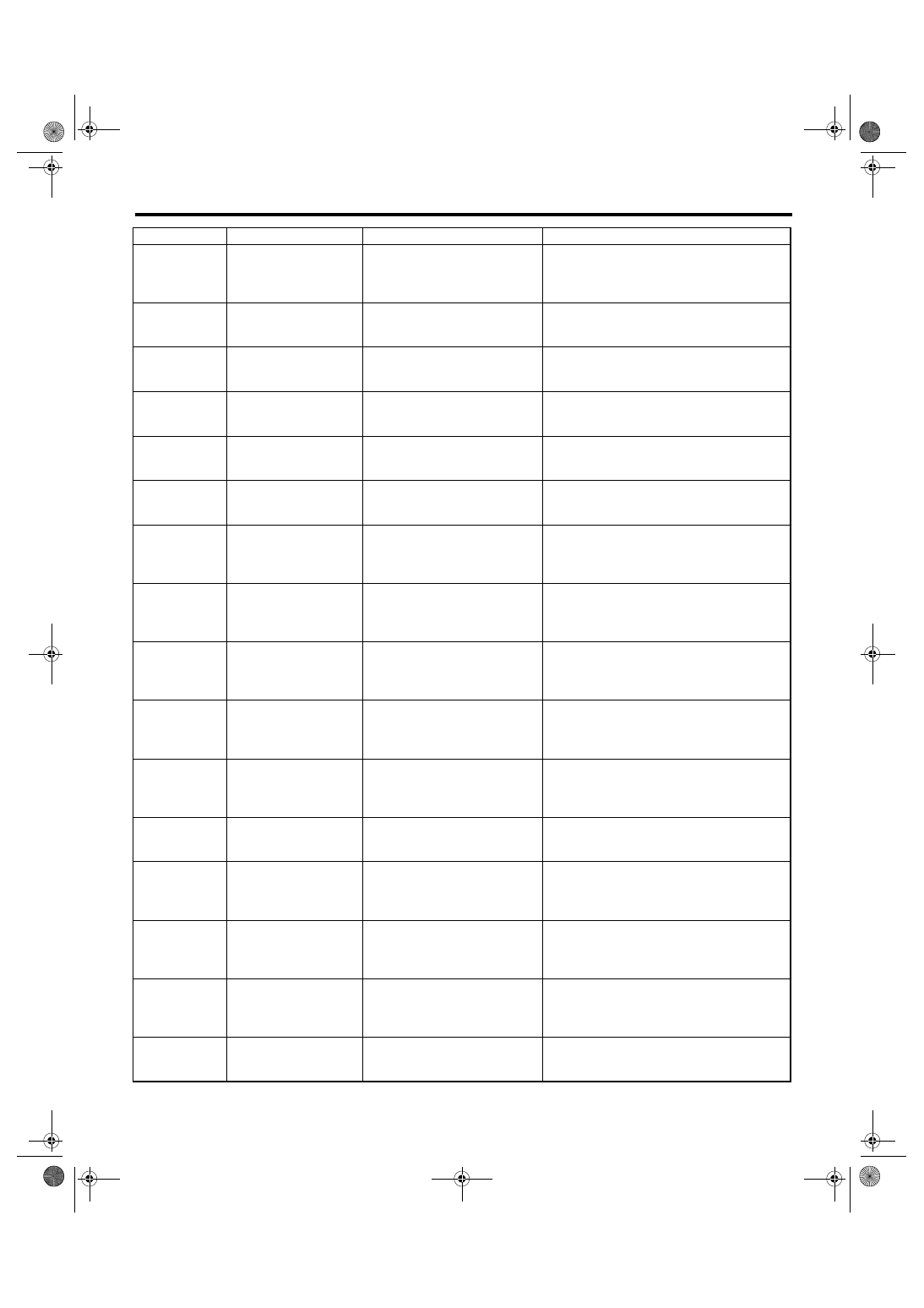
P0748
Pressure Control Sole-
noid “A” Electrical
Line pressure linear solenoid is
faulty or output signal circuit is
open or shorted.
P0753
Shift Solenoid “A” Elec-
trical
Low clutch duty solenoid is faulty
or output signal circuit is open or
shorted.
P0758
Shift Solenoid “B” Elec-
trical
2-4 brake duty solenoid is faulty
or output signal circuit is open or
shorted.
P0763
Shift Solenoid “C” Elec-
trical
High clutch duty solenoid is faulty
or output signal circuit is open or
shorted.
P0768
Shift Solenoid “D” Elec-
trical
Low & reverse clutch duty sole-
noid is faulty or output signal cir-
cuit is open or shorted.
P0801
Reverse Inhibit Control
Circuit
Shift lock solenoid is faulty or out-
put signal circuit is open or
shorted.
P1706
AT Vehicle Speed Sen-
sor Circuit Malfunction
(Rear Wheel)
Rear vehicle speed sensor is
faulty or input signal circuit is
open or shorted.
P1707
AT AWD Solenoid Valve
Circuit Malfunction
Transfer duty solenoid is faulty or
output signal circuit is open or
shorted.
P1708
Throttle Position Sensor
Circuit Low Input
Accelerator pedal position sen-
sor is faulty or input signal circuit
is open.
P1709
Throttle Position Sensor
Circuit High Input
Accelerator pedal position sen-
sor is faulty or input signal circuit
is shorted.
P1714
Throttle Position Sensor
Power Supply Circuit
Accelerator pedal position sen-
sor is faulty or input signal circuit
is open or shorted.
P1718
CAN Communication
Circuit
CAN communication circuit is
open or shorted
P1760
Lateral Acceleration
Sensor Performance
Problem
Lateral G sensor malfunction
P1761
Lateral Acceleration
Sensor Circuit Low
Lateral G sensor is faulty or input
signal circuit is open.
P1762
Lateral Acceleration
Sensor Circuit High
Lateral G sensor is faulty or input
signal circuit is shorted.
P1817
Sports Mode Switch Cir-
cuit
SPORT mode and manual mode
switch is faulty or input signal cir-
cuit is open or shorted.
DTC
Item
Contents of diagnosis
Reference target
Нет комментариевНе стесняйтесь поделиться с нами вашим ценным мнением.
Текст