Subaru Legacy (2005 year). Service manual — part 830
PARKING BRAKE
PB
Page
General Description . . . . . . . . . . . . . . . . . . . . . 2
Parking Brake Lever. . . . . . . . . . . . . . . . . . . . . 4
Parking Brake Cable . . . . . . . . . . . . . . . . . . . . ...5
Parking Brake Assembly (Rear Disc Brake) . . . . . . . . . . . ...6
General Diagnostic Table. . . . . . . . . . . . . . . . . . . 9
PB-2
PARKING BRAKE
General Description
1. General Description
A: SPECIFICATION
B: COMPONENT
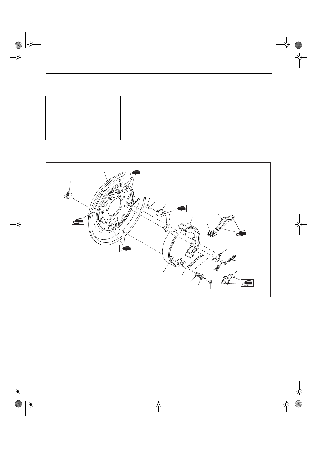
1. PARKING BRAKE (REAR DISC BRAKE)
Type
Mechanical on rear brakes, drum in disc
Effective drum
diameter
mm (in)
170 (6.69)
Lining dimensions
mm (in)
163.1
× 30.0 × 3.2
(6.421
× 1.181 × 0.126)
(length
× width ×
thickness)
Clearance adjustment
Manual adjustment
Lever stroke
notches/N (kgf, lbf)
5 to 6/200 (20.4, 45)
(1)
Back plate
(7)
Strut spring
(13)
Adjuster
(2)
Retainer
(8)
Strut
(14)
Shoe hold-down cup
(3)
Spring washer
(9)
Shoe guide plate
(15)
Shoe hold-down spring
(4)
Lever
(10)
Primary return spring
(16)
Shoe hold-down pin
(5)
Parking brake shoe (Primary)
(11)
Secondary return spring
(17)
Adjusting hole cover
(6)
Parking brake shoe (Secondary)
(12)
Adjusting spring
PB-00048
(16)
(10)
(13)
(11)
(9)
(6)
(2)
(1)
(17)
(3)
(4)
(7)
(8)
(14)
(15)
(12)
(5)
PB-3
PARKING BRAKE
General Description
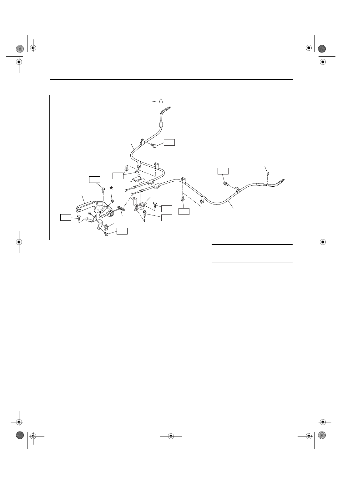
2. PARKING BRAKE CABLE
C: CAUTION
• Wear work clothing, including a cap, protective
goggles, and protective shoes during operation.
• Before removal, installation or disassembly, be
sure to clarify the failure. Avoid unnecessary re-
moval, installation, disassembly and replacement.
• Be careful not to burn yourself, because each
part on the vehicle is hot after running.
• Use SUBARU genuine grease etc. or the equiv-
alent. Do not mix grease etc. with that of another
grade or from other manufacturers.
• Be sure to tighten fasteners including bolts and
nuts to the specified torque.
• Place shop jacks or rigid racks at the specified
points.
• Before securing a part on a vice, place cushion-
ing material such as wood blocks, aluminum plate,
or shop cloth between the part and the vice.
• Keep grease etc. away from parking brake
shoes.
(1)
Parking brake lever
(6)
Clamp
Tightening torque: N
⋅
m (kgf-m, ft-lb)
(2)
Parking brake switch
(7)
Parking brake cable RH
T1: 18 (1.8, 13)
(3)
Adjusting nut (Self-locking nut)
(8)
Clamp
T2: 33 (3.4, 24.3)
(4)
Equalizer
(9)
Parking brake cable LH
(5)
Bracket
T1
T2
T1
T1
T1
(5)
(6)
(7)
(8)
(9)
(8)
T2
T1
T1
(1)
(3)
T1
(2)
(4)
PB-00113
PB-4
PARKING BRAKE
Parking Brake Lever
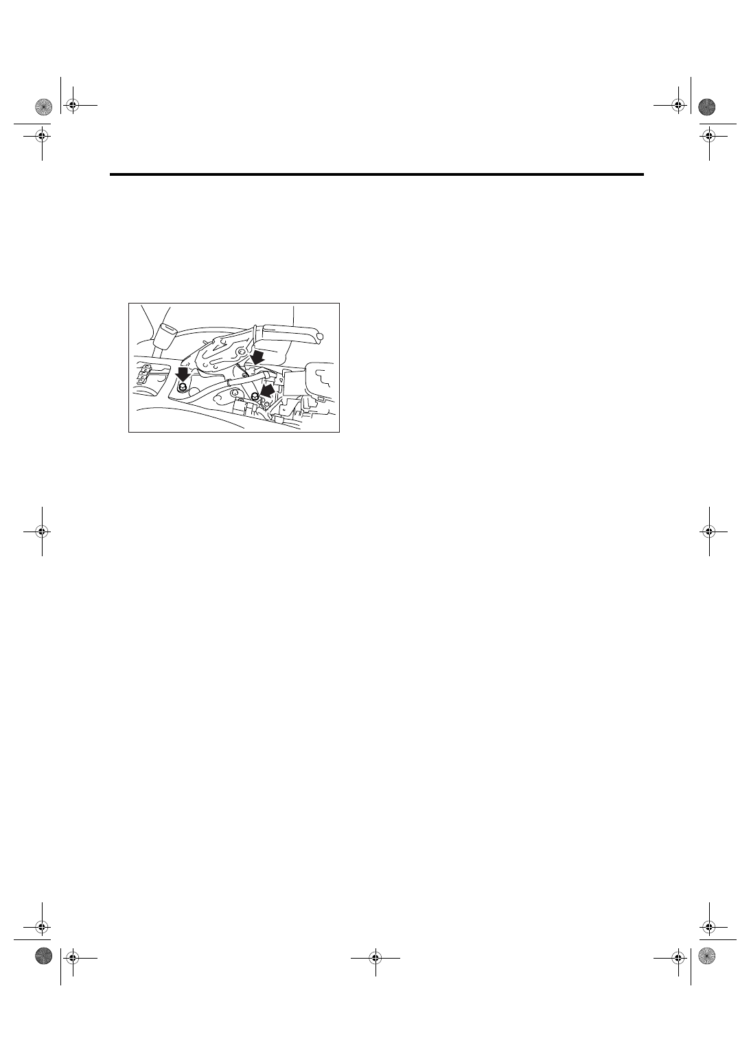
2. Parking Brake Lever
A: REMOVAL
1) Set the wheel stoppers to tires.
2) Remove the console box.
3) Disconnect the parking brake switch connector.
4) Remove the parking cable adjusting nut (self-
locking nut).
5) Remove the parking brake lever.
B: INSTALLATION
1) Install in the reverse order of removal.
Tightening torque:
Parking brake lever;
18 N
⋅
m (1.8 kgf-m, 13 ft-lb)
2) Install a new adjusting nut (self-locking nut).
3) Adjust the lever stroke. <Ref. to PB-4, ADJUST-
MENT, Parking Brake Lever.>
C: INSPECTION
1) Operate the parking brake lever 3 to 4 times and
return the lever fully.
2) While pulling the parking brake lever upward,
count the notches.
Lever stroke:
5 to 6 notches when pulled with a force of 200
N (20.4 kgf, 45 lbf)
If it is not within the specification, adjust the parking
brake. <Ref. to PB-8, ADJUSTMENT, Parking
Brake Assembly (Rear Disc Brake).>
D: ADJUSTMENT
Adjust the parking lever stroke. <Ref. to PB-8, LE-
VER STROKE, ADJUSTMENT, Parking Brake As-
sembly (Rear Disc Brake).>
PB-00053
Нет комментариевНе стесняйтесь поделиться с нами вашим ценным мнением.
Текст