Subaru Legacy (2005 year). Service manual — part 609
5AT(diag)-27
AUTOMATIC TRANSMISSION (DIAGNOSTICS)
Diagnostic Procedure for Subaru Select Monitor Communication
12.Diagnostic Procedure for Subaru Select Monitor Communication
A: COMMUNICATION FOR INITIALIZING IMPOSSIBLE
DIAGNOSIS:
Defective harness connector
TROUBLE SYMPTOM:
Subaru Select Monitor communication failure
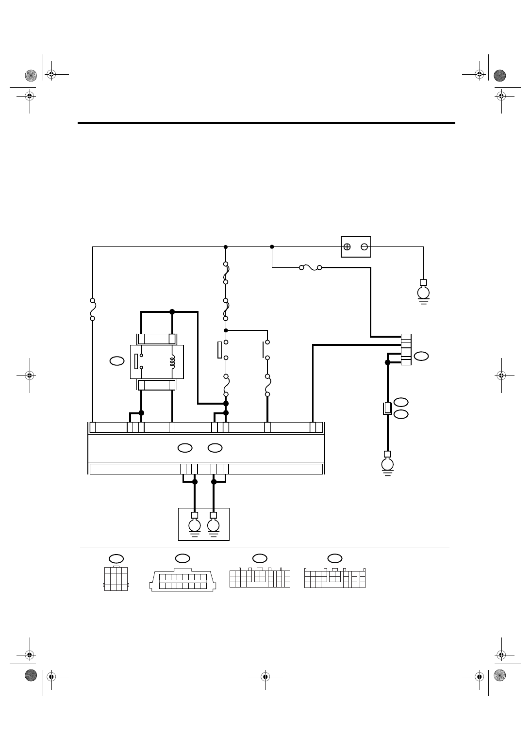
WIRING DIAGRAM:
AT-03173
B40
B54
B55
B21
B54
A:
B55
B357
B:
TCM
B40
E
F/B No.12
M/B No. 12
SBF-6
MAIN SBF
A1
A19
B21
B1
B10
A20
A5
A14
1 2
3 4 5 6
7 8
9 10 11 12 13 14 15 16
1
12
10
13
No.13
B21
E2
16
E
E
E
1 2 3 4
5 6 7 8
9 10 11 12
13 14 15 16
A:
B:
IGNITION
SWITCH
No.31
B2
A7
A8
A10
ACCESSORY
SWITCH
BATTERY
DATA LINK
CONNECTOR
TRANSMISSION
1 2
7
8
9
5 6
3 4
10 11 12
19 20 21
13
14 15
16
17
18
22
23
24
1 2 3 4
10 11 12
19 20 21
13
5 6
14 15
7
8
9
16
17
18
22
23
24
3
2
4
1
PVIGN
RELAY
5AT(diag)-28
AUTOMATIC TRANSMISSION (DIAGNOSTICS)
Diagnostic Procedure for Subaru Select Monitor Communication
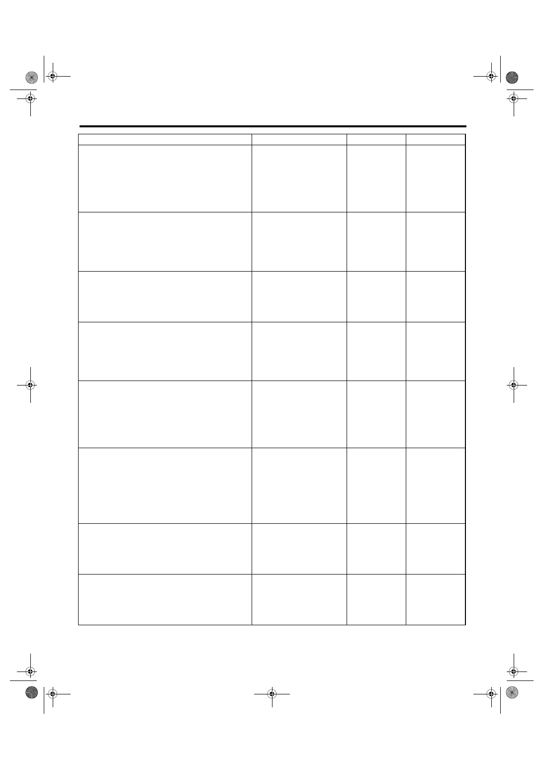
Step
Check
Yes
No
1
CHECK SUBARU SELECT MONITOR POW-
ER SUPPLY CIRCUIT.
Measure the voltage between data link con-
nector and chassis ground.
Connector & terminal
(B40) No. 1 (+) — Chassis ground (
−
):
Is the voltage more than 10 V? Go to step 2.
Repair the har-
ness connector
and connector
between battery
and data link con-
nector, and poor
contact in connec-
tor.
2
CHECK SUBARU SELECT MONITOR
GROUND CIRCUIT.
Measure the resistance of harness between
data link connector and chassis ground.
Connector & terminal
(B40) No. 12 — Chassis ground:
(B40) No. 13 — Chassis ground:
Is the resistance less than 1
Ω?
Repair the open
circuit of harness
between data link
connector and
ground terminal,
and poor contact
in connector.
3
CHECK COMMUNICATION OF SUBARU SE-
LECT MONITOR.
1) Turn the ignition switch to ON.
2) Using the Subaru Select Monitor, check
whether communication to transmission sys-
tems can be executed normally.
Are the name and year of sys-
tem displayed on Subaru
Select Monitor?
4
CHECK COMMUNICATION OF SUBARU SE-
LECT MONITOR.
1) Turn the ignition switch to OFF.
2) Disconnect the TCM connector.
3) Turn the ignition switch to ON.
4) Check whether communication to engine
systems can be executed normally.
Are the name and year of sys-
tem displayed on Subaru
Select Monitor?
5
CHECK COMMUNICATION OF SUBARU SE-
LECT MONITOR.
1) Turn the ignition switch to OFF.
2) Connect the TCM connector.
3) Disconnect the ECM connector.
4) Turn the ignition switch to ON.
5) Check whether communication to transmis-
sion systems can be executed normally.
Are the name and year of sys-
tem displayed on Subaru
Select Monitor?
Inspect the ECM.
6
CHECK HARNESS CONNECTOR BETWEEN
EACH CONTROL MODULE AND DATA LINK
CONNECTOR.
1) Turn the ignition switch to OFF.
2) Disconnect the TCM and ECM connector.
3) Measure the resistance between TCM con-
nector and chassis ground.
Connector & terminal
(B40) No. 10 — Chassis ground:
Is the resistance more than 1
M
Ω?
Check harness
and connector
between each con-
trol module and
data link connec-
tor.
7
CHECK OUTPUT SIGNAL OF TCM.
1) Turn the ignition switch to ON.
2) Measure the voltage between TCM and
chassis ground.
Connector & terminal
(B40) No. 10 (+) — Chassis ground (
−
):
Is the voltage more than 1 V?
Check harness
and connector
between each con-
trol module and
data link connec-
tor.
8
CHECK HARNESS CONNECTOR BETWEEN
TCM AND DATA LINK CONNECTOR.
Measure the resistance between TCM connec-
tor and data link connector.
Connector & terminal
(B54) No. 20 — (B40) No. 10:
Is the resistance less than 1
Ω?
Repair the har-
ness and connec-
tor between TCM
and data link con-
nector.
5AT(diag)-29
AUTOMATIC TRANSMISSION (DIAGNOSTICS)
Diagnostic Procedure for Subaru Select Monitor Communication
9
CHECK INSTALLATION OF TCM CONNEC-
TOR.
Turn the ignition switch to OFF.
Is TCM connector connected
to TCM?
Connect the TCM
connector to TCM.
10
CHECK INSTALLATION OF TRANSMISSION
HARNESS CONNECTOR.
Is the transmission harness
connector connected to bulk-
head harness connector?
Connect the bulk-
head harness con-
nector to
transmission har-
ness connector.
11
CHECK POOR CONTACT IN CONNECTORS. Is there poor contact in control
module power supply and data
link connector?
Repair the poor
contact.
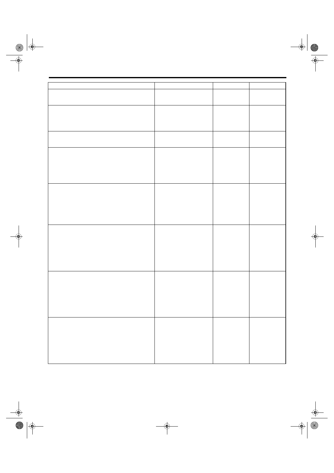
12
CHECK POWER SUPPLY OF TCM.
1) Disconnect the connector from TCM.
2) Turn the ignition switch to ON.
3) Measure the voltage between TCM con-
nector and chassis ground.
Connector & terminal
(B54) No. 1 (+) — Chassis ground (
−
):
Is the voltage 10 — 13 V?
13
CHECK FUSE.
1) Turn the ignition switch to OFF.
2) Remove the fuse M/B (No. 12).
Is the fuse M/B (No. 12) blown
out?
Repair the open
circuit of harness
between fuse M/B
(No. 12) and TCM,
or fuse M/B (No.
12) and battery,
and poor contact
in connector.
14
CHECK HARNESS.
Measure the resistance between TCM connec-
tor and chassis ground.
Connector & terminal
(B54) No. 1 — Chassis ground:
Is the resistance less than 10
Ω?
Replace the fuse
M/B (No. 12). If the
replaced fuse M/B
(No. 12) has blown
out easily, repair
the short circuit of
harness between
fuse M/B (No. 12)
and TCM.
Replace the fuse
M/B (No. 12).
15
CHECK IGNITION POWER SUPPLY CIR-
CUIT.
1) Turn the ignition switch to ON (engine
OFF).
2) Measure the ignition power supply voltage
between TCM connector and chassis ground.
Connector & terminal
(B55) No. 1 (+) — Chassis ground (
−
):
(B55) No. 10 (+) — Chassis ground (
−
):
Is the voltage 10 — 13 V?
16
CHECK FUSE.
Remove the fuse F/B (No. 12).
Is the fuse F/B (No. 12) blown
out?
Replace the fuse
F/B (No. 12). If the
replaced fuse F/B
(No. 12) has blown
out easily, repair
the short circuit of
harness between
fuse F/B (No. 12)
and TCM.
Repair the open
circuit of harness
between fuse F/B
(No. 12) and TCM,
or fuse F/B (No.
12) and battery,
and poor contact
in connector.
Step
Check
Yes
No
5AT(diag)-30
AUTOMATIC TRANSMISSION (DIAGNOSTICS)
Diagnostic Procedure for Subaru Select Monitor Communication
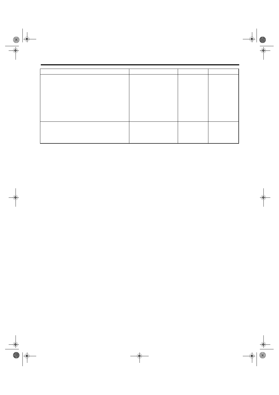
17
CHECK HARNESS CONNECTOR BETWEEN
TCM AND TRANSMISSION.
1) Turn the ignition switch to OFF.
2) Disconnect the connectors from TCM.
3) Measure the resistance of harness
between TCM and transmission ground.
Connector & terminal
(B54) No. 19 — Transmission ground:
(B55) No. 21 — Transmission ground:
(B54) No. 5 — Transmission ground:
(B54) No. 14 — Transmission ground:
Is the resistance more than 1
M
Ω?
Repair the open
circuit of harness
between TCM and
transmission
ground, and poor
contact in connec-
tor.
18
CHECK POOR CONTACT IN CONNECTORS. Is there poor contact in TCM
power supply, ground and data
link connector?
Repair the con-
nector.
Replace the TCM.
<Ref. to 5AT-61,
Transmission Con-
trol Module
(TCM).>
Step
Check
Yes
No
Нет комментариевНе стесняйтесь поделиться с нами вашим ценным мнением.
Текст