Subaru Legacy (2005 year). Service manual — part 358

EN(H4DOTC)(diag)-201
ENGINE (DIAGNOSTICS)
Diagnostic Procedure with Diagnostic Trouble Code (DTC)
8
CHECK ACCELERATOR PEDAL POSITION
SENSOR.
1) Measure the resistance of accelerator
pedal position sensor.
Terminals
No. 2 — No. 6:
2) Check the measured value is within the
specification with the accelerator pedal
depressed.
Is the resistance 0.28 — 1.68
k
Ω?
Repair the poor
contact in ECM
connector.
Replace the ECM
if defective. <Ref.
to FU(H4DOTC)-
34, Engine Con-
trol Module
(ECM).>
Replace the accel-
erator pedal posi-
tion sensor.
Step
Check
Yes
No
EN(H4DOTC)(diag)-202
ENGINE (DIAGNOSTICS)
Diagnostic Procedure with Diagnostic Trouble Code (DTC)
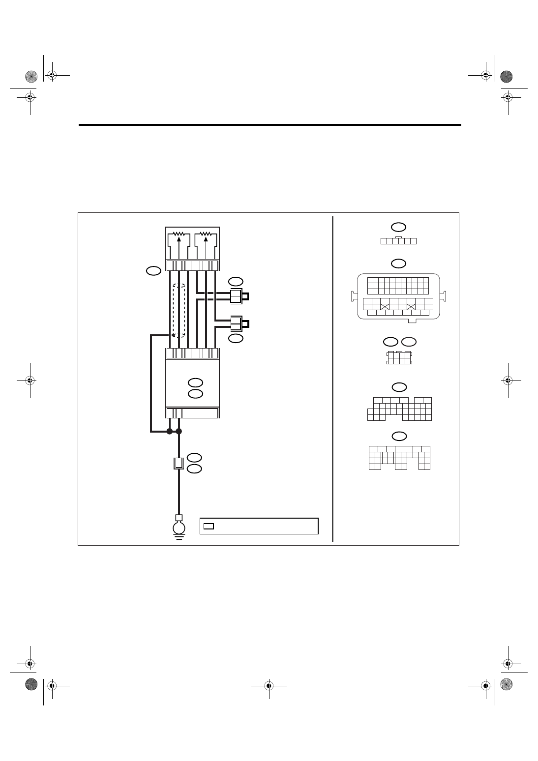
BT:DTC P2128 THROTTLE/PEDAL POSITION SENSOR/SWITCH “E” CIRCUIT
HIGH INPUT
DTC DETECTING CONDITION:
Immediately at fault recognition
TROUBLE SYMPTOM:
• Erroneous idling
• Poor driving performance
WIRING DIAGRAM:
EN-03546
B315
B21
E
C:
ECM
B136
B137
D:
C:
B136
B137
D:
B83
B315
*
*
3
5
4
1
2
6
C15
C17
C34
C16
C28
C35
D1
D2
1 2 3 4 5 6
B122
1 2 3 4
5 6 7 8
5
6
7 8
2
1
9
4
3
10
24
22 23
25
11 12 13 14 15
26 27
28
16
17 18 19 20 21
33 34
29
32
30
31
35
5
6
7
8
2
1
9
4
3
10
22 23
11 12 13 14 15
24 25
26
16 17
18 19 20 21
27
28 29
30 31
MAIN
SUB
ACCELERATOR
PEDAL POSITION
SENSOR
B122
7
4
36
1 2 3 4
12 13 14 15
5 6 7 8
16 17 18 19
9 10 11
20 21 22
23 24 25 26 27 28 29 30 31 32 33
35
34
37
36
39
38
41
40
43
42
44
45
47
46
49
48
51
50
53
52
54
B21
E2
B83
*
: TERMINAL No. RANDOM ARRANGEMENT

EN(H4DOTC)(diag)-203
ENGINE (DIAGNOSTICS)
Diagnostic Procedure with Diagnostic Trouble Code (DTC)
Step
Check
Yes
No
1
CHECK ACCELERATOR PEDAL POSITION
SENSOR OUTPUT.
1) Turn the ignition switch to ON.
2) Read the data of sub accelerator pedal
position sensor signal using Subaru Select
Monitor.
NOTE:
• Subaru Select Monitor
For detailed operation procedure, refer to
“READ CURRENT DATA FOR ENGINE”. <Ref.
to EN(H4DOTC)(diag)-24, Subaru Select Mon-
itor.>
Is the voltage less than 4.8 V? Go to step 2.
2
CHECK POOR CONTACT.
Check poor contact in connector between
ECM and accelerator pedal position sensor.
Is there poor contact?
Repair the poor
contact.
Temporary poor
contact occurred,
but it is normal at
present.
3
CHECK HARNESS BETWEEN ECM AND AC-
CELERATOR PEDAL POSITION SENSOR.
1) Turn the ignition switch to OFF.
2) Disconnect the connector from ECM.
3) Disconnect the connectors from accelerator
pedal position sensor.
4) Measure the resistance between ECM con-
nector and accelerator pedal position sensor
connector.
Connector & terminal
(B136) No. 35 — (B315) No. 6:
Is the resistance less than 1
Ω?
Repair the open
circuit of harness
connector.
4
CHECK HARNESS BETWEEN ECM AND AC-
CELERATOR PEDAL POSITION SENSOR.
1) Connect the ECM connector.
2) Measure the resistance between accelera-
tor pedal position sensor connector and chas-
sis ground.
Connector & terminal
(B315) No. 6 — Chassis ground:
Is the resistance less than 5
Ω?
Repair the poor
contact in ECM
connector.
Replace the ECM
if defective. <Ref.
to FU(H4DOTC)-
34, Engine Con-
trol Module
(ECM).>
5
CHECK HARNESS BETWEEN ECM AND AC-
CELERATOR PEDAL POSITION SENSOR.
1) Connect the ECM connector.
2) Turn the ignition switch to ON.
3) Measure the voltage between accelerator
pedal position sensor connector and chassis
ground.
Connector & terminal
(B315) No. 2 (+) — Chassis ground (
−
):
Is the voltage less than 6 V?
Repair the battery
short circuit of har-
ness between
ECM connector
and accelerator
pedal position sen-
sor connector.
6
CHECK HARNESS BETWEEN ECM AND AC-
CELERATOR PEDAL POSITION SENSOR.
1) Turn the ignition switch to OFF.
2) Measure the resistance between ECM con-
nector terminals.
Connector & terminal
(B137) No. 28 — (B137) No. 15:
(B137) No. 28 — (B137) No. 16:
Is the resistance more than 1
M
Ω?
Repair the poor
contact in acceler-
ator pedal position
sensor connector.
Replace the accel-
erator pedal posi-
tion sensor if
defective.
Repair the short
circuit to sensor
power supply.
EN(H4DOTC)(diag)-204
ENGINE (DIAGNOSTICS)
Diagnostic Procedure with Diagnostic Trouble Code (DTC)
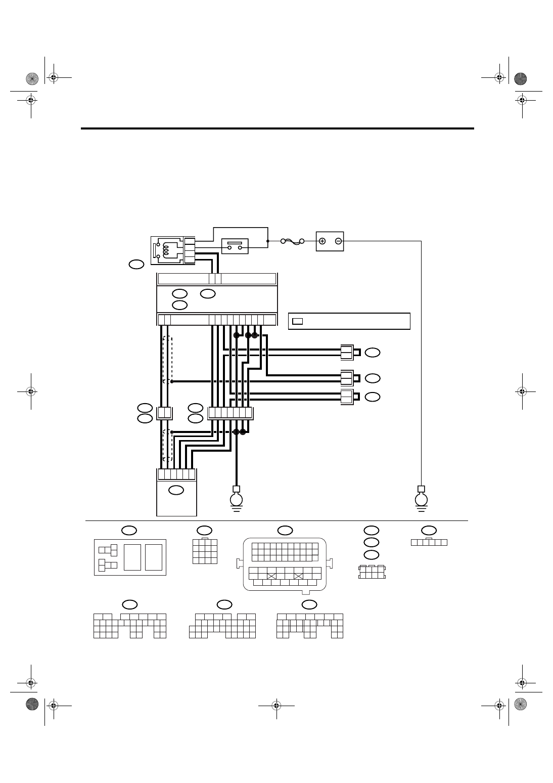
BU:DTC P2135 THROTTLE/PEDAL POSITION SENSOR/SWITCH “A” / “B”
VOLTAGE CORRELATION
DTC DETECTING CONDITION:
Immediately at fault recognition
TROUBLE SYMPTOM:
• Erroneous idling
• Poor driving performance
WIRING DIAGRAM:
EN-03524
SBF-7
B135
B:
B137
B136
D:
B362
B84
B138
B122
E1
B20
E57
C:
B135
B362
B20
B21
E57
B84
B122
B138
B137
B136
E
E
D6
B35
16
15
*
*
*
*
7
3
E2
B21
39
38
19
20
35
36
37
4
6
1
2
3
5
D4
D5
C35
C16
B1
B4
D1
D2
D3
C29
C18
5
8
7
6
1 2 3 4
5 6 7 8
9 10 11 12
13 14 15 16
1 2
7 8
3
4
5
6
1 2 3 4 5 6 7 8 9 10 11
12 13 14 15 16 17 18 19 20 21 22
23 24 25
34 35
36 37 38 39 40 41
48 49
50 51 52 53 54
42 43
44 45
46 47
26 27 28 29 30 31 32 33
1 2 3 4
5 6 7 8
1 2 3 4 5 6
1
2
7
8 9
5
6
3
4
10 11 12
19 20 21
29
30 31
13 14 15 16 17
27
28
18
22 23
24 25
26
1
2
7
8 9
5
6
3
4
10 11 12
19
20 21
29 30 31
13 14 15 16 17
27
28
18
22 23
24 25
26
32 33
34 35
1
2
8 9
5
6
3
4
10 11 12
19 20 21
29 30
31
13 14 15 16
17
27
28
18
22 23 24 25 26
7
32 33 34 35
B:
D:
C:
ECM
BATTERY
MAIN RELAY
ELECTRONIC
THROTTLE
CONTROL RELAY
ELECTRONIC
THROTTLE
CONTROL
*
: TERMINAL No. RANDOM ARRANGEMENT
Нет комментариевНе стесняйтесь поделиться с нами вашим ценным мнением.
Текст