Subaru Legacy (2005 year). Service manual — part 712
FS-19
FRONT SUSPENSION
Front Arm
C: DISASSEMBLY
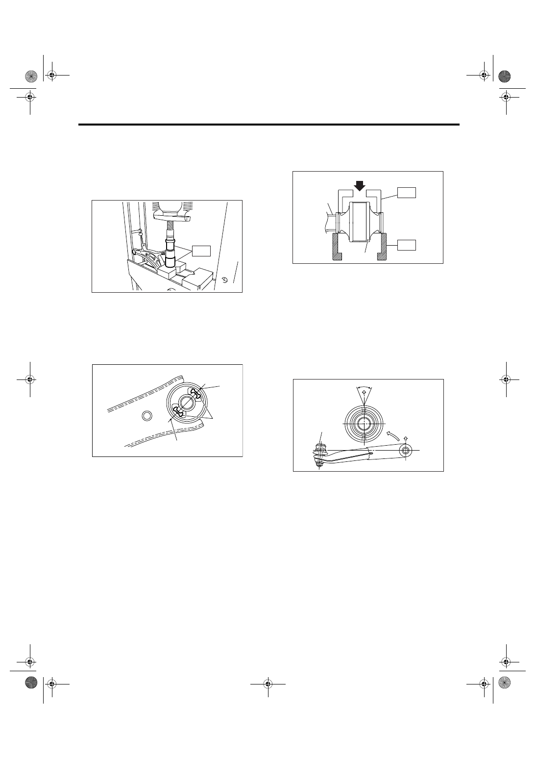
1. FRONT BUSHING
Using the ST and a press, remove the front bush-
ing.
ST
927680000
INSTALLER & REMOVER
SET
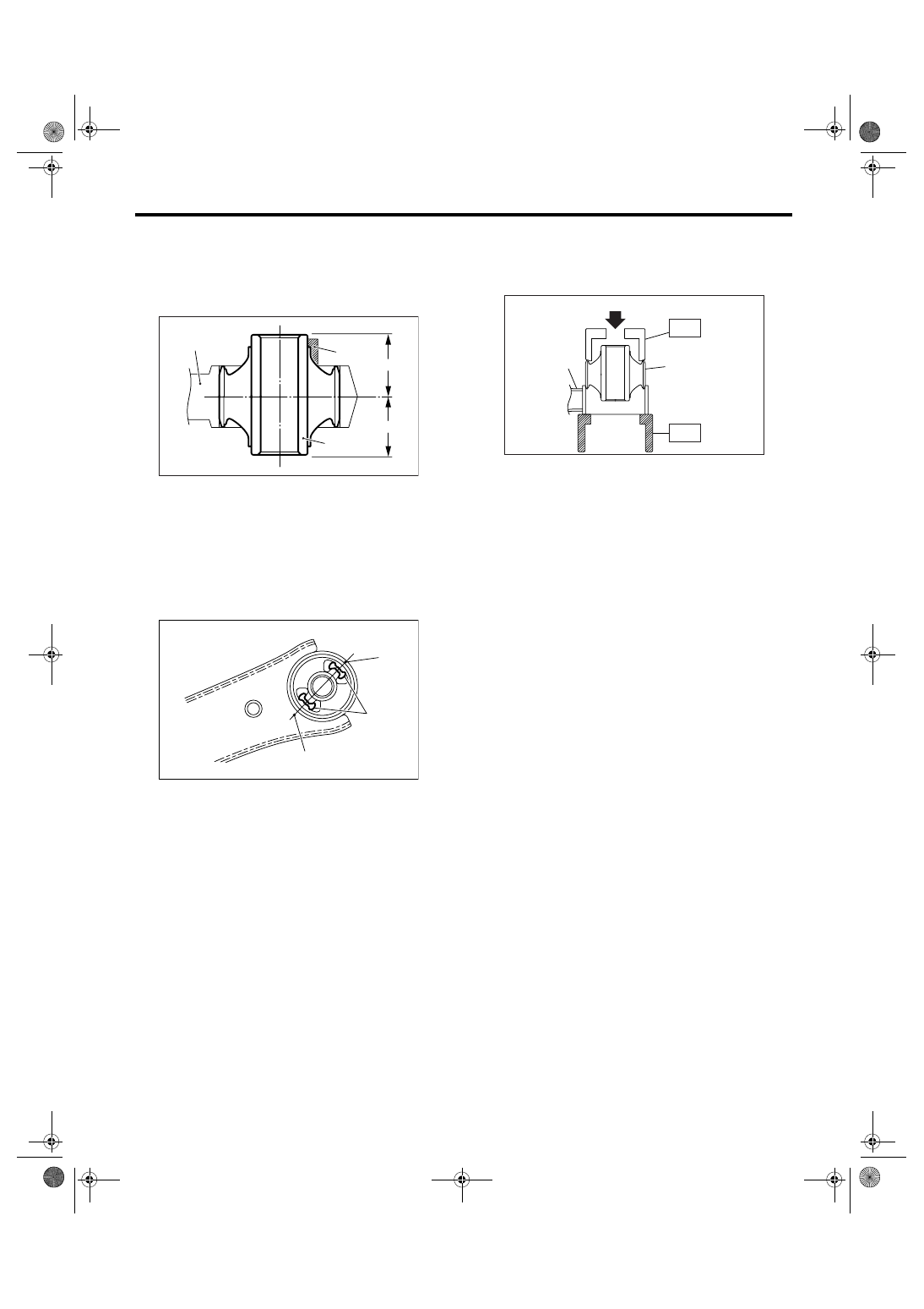
2. REAR BUSHING
1) Put an alignment mark on the front arm based on
the center of rear bushing recess portion.
CAUTION:
Always put an alignment mark for aligning the
position on bushing installation.
2) Using the ST and a press, remove the rear bush-
ing.
ST1
20299AG000 REMOVER
ST2
20299AG010 BASE
D: ASSEMBLY
1. FRONT BUSHING
Assemble in the reverse order of disassembly.
CAUTION:
Install the front bushing in proper direction as
shown in the figure.
(1) Put an alignment mark.
(2) Recess portion
ST
FS-00110
FS-00136
(2)
(1)
(1)
(1) Press
(2) Front arm
(3) Rear bushing
(1) Face the bushing toward the center of ball joint
(2) Ball joint
(3)
±3°
(1)
(2)
(3)
ST2
ST1
FS-00126
FS-00102
(1)
(2)
(3)
FS-20
FRONT SUSPENSION
Front Arm
2. REAR BUSHING
1) Install the rear bushing with its longer inner cyl-
inder faced upward and its shorter one faced down-
ward and protruding part rearward as shown in the
figure.
2) Align the center of rear bushing recess portion
with the aligning mark on the front arm.
3) Using the ST and a press, install the rear bush-
ing.
ST1
20299AG000 REMOVER
ST2
20299AG010 BASE
E: INSPECTION
1) Check the front arm for wear, damage or cracks,
and correct or replace if defective.
2) Check the bushing for crack, fatigue or damage.
(1) Front arm
(2) Bushing inner cylinder
(3) Longer
(4) Shorter
(5) Protrusion portion
(1) Alignment mark
(2) Recess portion
FS-00113
(2)
(1)
(3)
(4)
(5)
FS-00136
(2)
(1)
(1)
(1) Press
(2) Front arm
(3) Rear bushing
FS-00127
(1)
(2)
(3)
ST2
ST1
FS-21
FRONT SUSPENSION
Front Strut
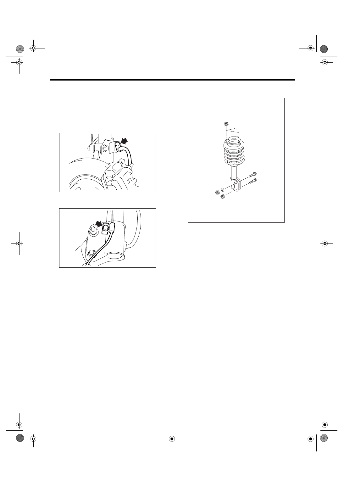
7. Front Strut
A: REMOVAL
1) Lift-up the vehicle, and then remove the front
wheels.
2) Put an alignment mark on the camber adjusting
bolt and strut.
3) Remove the bolt securing brake hose from strut.
4) Remove the bolt securing ABS wheel speed
sensor harness.
5) Remove the two bolts securing housing to strut.
NOTE:
While holding the head of adjusting bolt, loosen the
self-locking nut.
6) Remove the three nuts securing strut mount to
body.
B: INSTALLATION
1) Install the strut mount at the upper side of strut to
body, and tighten it with new self-locking nuts.
Tightening torque:
20 N
⋅
m (2.0 kgf-m, 14.5 ft-lb)
2) Align alignment marks on the camber adjusting
bolt and strut.
Using new self-locking nuts, install the strut to
housing.
NOTE:
While holding the head of adjusting bolt, tighten the
self-locking nut.
Tightening torque:
175 N
⋅
m (17.8 kgf-m, 129 ft-lb)
3) Secure the ABS wheel speed sensor harness to
strut.
Tightening torque:
33 N
⋅
m (3.4 kgf-m, 24.3 ft-lb)
4) Install the bolts which secure brake hose to strut.
Tightening torque:
33 N
⋅
m (3.4 kgf-m, 24.3 ft-lb)
5) Install the front wheels.
NOTE:
Inspect the wheel alignment and adjust if neces-
sary.
FS-00037
FS-00038
FS-00039
FS-22
FRONT SUSPENSION
Front Strut
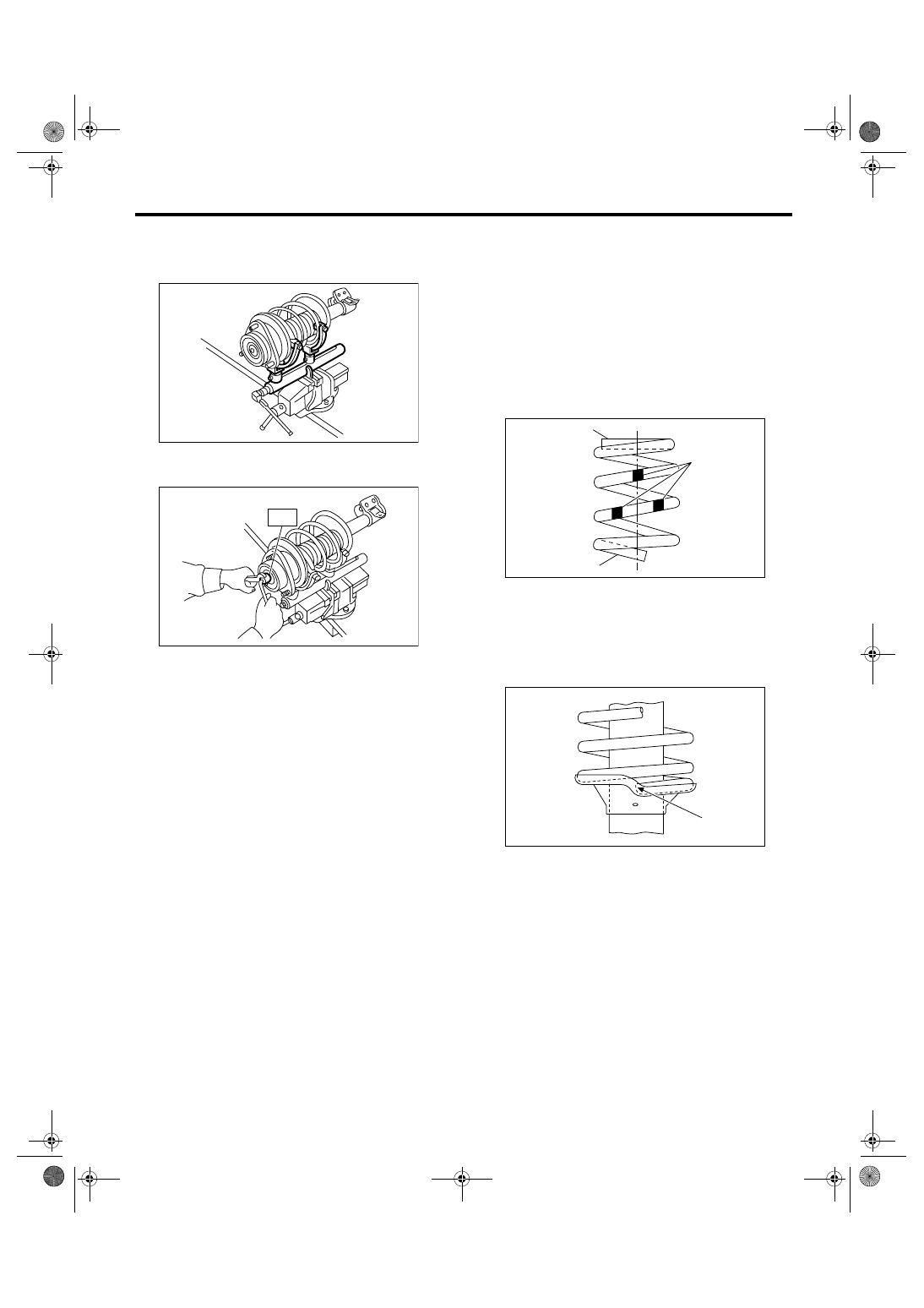
C: DISASSEMBLY
1) Using a coil spring compressor, compress the
coil spring.
2) Using the ST, remove the self-locking nut.
ST
20399AG000 STRUT MOUNT SOCKET
3) Remove the strut mount and upper spring seat
from strut.
4) Gradually decrease the compression force of
compressor, and remove the coil spring.
5) Remove the dust cover and helper spring.
D: ASSEMBLY
1) Before installing the coil spring, strut mount, etc.
on strut, check for the presence of air in the damp-
ening force generating mechanism of the strut
since air prevents proper dampening force produc-
tion.
2) Check for presence of air
(1) Place the strut vertically with the piston rod
facing up.
(2) Move the piston rod to the center of its entire
stroke.
(3) While holding the piston rod end with finger-
tips, move the rod up and down.
(4) If the piston rod moves at least 10 mm (0.39
in) in the former step, purge air from the strut.
3) Air purging procedure
(1) Place the strut vertically with the piston rod
facing up.
(2) Fully extend the piston rod.
(3) With the piston rod fully extended, place the
piston rod side down. The strut must stand ver-
tically.
(4) Fully contract the piston rod.
(5) Repeat 3 to 4 times from the step (1).
NOTE:
After completely purging air from the strut, be sure
to place the strut with the piston rod facing up. If the
strut is laid down and set, check for the entry of air
in accordance with “Check for the presence of air”.
4) Using a coil spring compressor, compress the
coil spring.
NOTE:
Make sure that the vertical installing direction of coil
spring is as shown in the figure.
5) Set the coil spring correctly so that its end face
fits well into the spring seat as shown in the figure.
6) Install the helper and dust cover to piston rod.
FS-00040
FS-00041
ST
(1) Diameter is small (Upper part)
(2) Identification paint
(3) Diameter is large (Bottom part)
(1) Coil spring end face
FS-00042
(2)
(1)
(3)
FS-00043
(1)
Нет комментариевНе стесняйтесь поделиться с нами вашим ценным мнением.
Текст