Subaru Legacy (2005 year). Service manual — part 801
VDC(diag)-69
VEHICLE DYNAMICS CONTROL (VDC) (DIAGNOSTICS)
Diagnostic Procedure with Diagnostic Trouble Code (DTC)
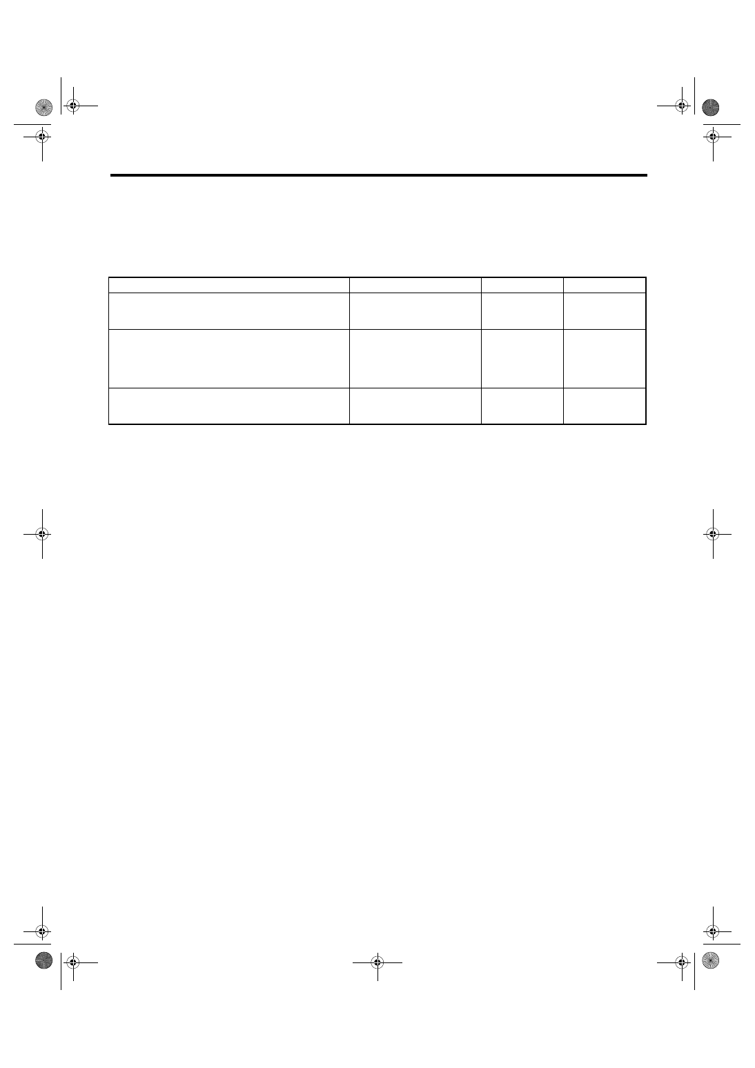
AE:DTC C0045 AT CONTROL MODULE MALFUNCTION
DTC DETECTING CONDITION:
Defective TCM
TROUBLE SYMPTOM:
• ABS does not operate.
• VDC does not operate.
Step
Check
Yes
No
1
CHECK AT SYSTEM.
1) Start the engine.
2) Check the DTC in AT system.
Is DTC of AT system dis-
played?
Repair the AT sys-
tem.
2
CHECK VDCCM&H/U.
1) Connect all the connectors.
2) Perform the clear memory mode.
3) Perform the inspection mode.
4) Read the DTC.
Is the same DTC displayed?
Replace the
VDCCM&H/U.
3
CHECK OTHER DTC DETECTION.
Is any other DTC displayed?
Perform the diag-
nosis according to
DTC.
It results from a
temporary noise
interference.
VDC(diag)-70
VEHICLE DYNAMICS CONTROL (VDC) (DIAGNOSTICS)
Diagnostic Procedure with Diagnostic Trouble Code (DTC)
AF:DTC C0047 IMPROPER CAN COMMUNICATION
DTC DETECTING CONDITION:
CAN communication line circuit is open or shorted.
TROUBLE SYMPTOM:
• ABS does not operate.
• VDC does not operate.
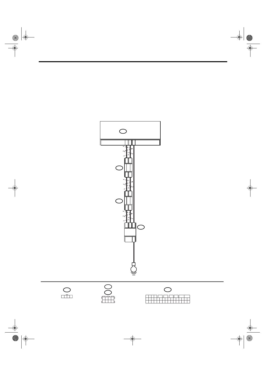
WIRING DIAGRAM:
• LHD model
VDC00327
30
29
13
B231
B234
E
2
4
1
3
3
1
4
2
B310
B310
VDCCM & H/U
1 2 3 4
11 12 13 14
27 28 29 30
15 16 17 18
31 32 33 34
19 20 21 22
35 36 37 38
23 24 25 26
39 40 41 42
5
6
7
8
9
10
1 2 3 4
B231
TWISTED WIRE
STEERING
ANGLE SENSOR
B234
3 4
5 6
1 2
7 8
B352
3
1
4
2
B352
VDC(diag)-71
VEHICLE DYNAMICS CONTROL (VDC) (DIAGNOSTICS)
Diagnostic Procedure with Diagnostic Trouble Code (DTC)
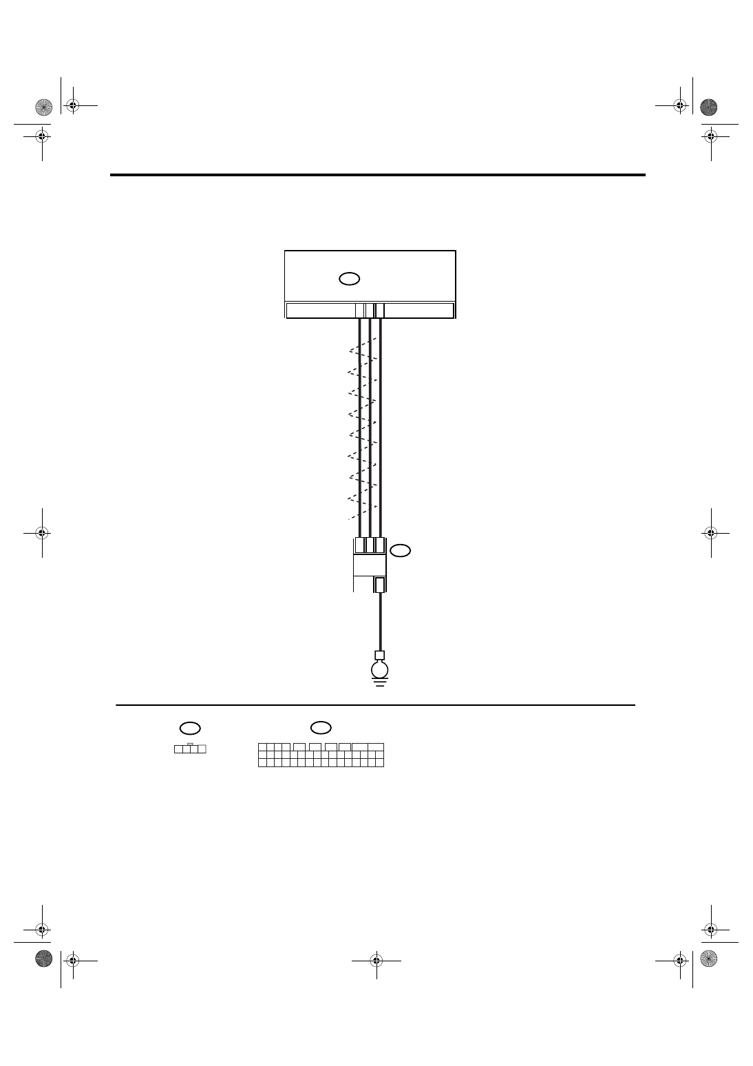
• RHD model
VDC00247
30
29
13
B231
E
2
4
1
3
B310
B310
VDCCM & H/U
1 2 3 4
11 12 13 14
27 28 29 30
15 16 17 18
31 32 33 34
19 20 21 22
35 36 37 38
23 24 25 26
39 40 41 42
5
6
7
8
9
10
1 2 3 4
B231
TWISTED WIRE
STEERING
ANGLE SENSOR
VDC(diag)-72
VEHICLE DYNAMICS CONTROL (VDC) (DIAGNOSTICS)
Diagnostic Procedure with Diagnostic Trouble Code (DTC)
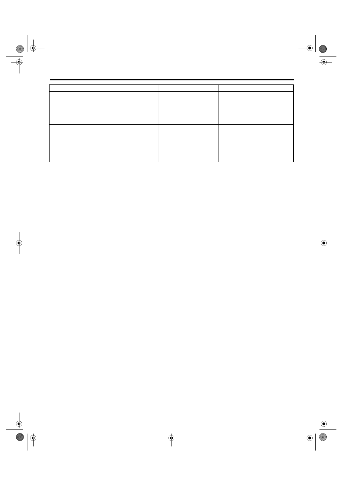
Step
Check
Yes
No
1
CHECK LAN SYSTEM.
Perform the diagnosis for LAN system. <Ref. to
LAN(diag)-24, OPERATION, Read Diagnostic
Trouble Code (DTC).>
Is there any fault in LAN sys-
tem?
Perform the diag-
nosis according to
DTC for LAN sys-
tem.
2
CHECK POOR CONTACT IN CONNECTORS. Is there poor contact in
VDCCM&H/U connector?
Repair the con-
nector.
3
CHECK VDCCM&H/U.
1) Connect all the connectors.
2) Perform the clear memory mode.
3) Perform the inspection mode.
4) Read the DTC.
Is the same DTC displayed?
Replace the
VDCCM&H/U.
<Ref. to VDC-7,
VDC Control Mod-
ule and Hydraulic
Control Unit
(VDCCM&H/U).>
Temporary poor
contact occurs.
Нет комментариевНе стесняйтесь поделиться с нами вашим ценным мнением.
Текст