Subaru Legacy (2005 year). Service manual — part 198

EN(H4SO 2.5)(diag)-77
ENGINE (DIAGNOSTICS)
List of Diagnostic Trouble Code (DTC)
P1572
IMM Circuit Failure (Except Antenna
Circuit)
P1574
Key Communication Failure
P1576
EGI Control Module EEPROM
P1577
IMM Control Module EEPROM
P1578
Meter Failure
P2100
Throttle Actuator Control Motor Cir-
cuit/Open
P2101
Throttle Actuator Control Motor Cir-
cuit Range/Performance
P2102
Throttle Actuator Control Motor Cir-
cuit Low
P2103
Throttle Actuator Control Motor Cir-
cuit High
P2109
Throttle/Pedal Position Sensor A
Minimum Stop Performance
P2111
Throttle Actuator Control System -
Stuck Open
P2122
Throttle/Pedal Position Sensor/
Switch “D” Circuit Low Input
P2123
Throttle/Pedal Position Sensor/
Switch “D” Circuit High Input
P2127
Throttle/Pedal Position Sensor/
Switch “E” Circuit Low Input
P2128
Throttle/Pedal Position Sensor/
Switch “E” Circuit High Input
P2135
Throttle/Pedal Position Sensor/
Switch “A”/“B” Voltage Correlation
P2138
Throttle/Pedal Position Sensor/
Switch “D”/“E” Voltage Correlation
P2503
Charging System Voltage Low
P2504
Charging System Voltage High
DTC
Item
Reference
EN(H4SO 2.5)(diag)-78
ENGINE (DIAGNOSTICS)
Diagnostic Procedure with Diagnostic Trouble Code (DTC)
18.Diagnostic Procedure with Diagnostic Trouble Code (DTC)
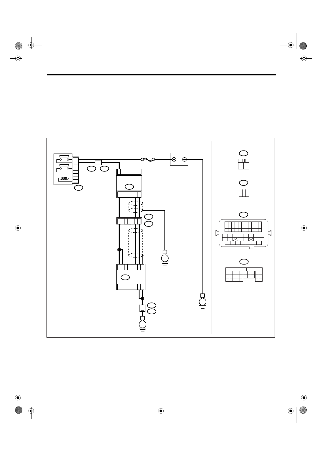
A: DTC P0030 HO2S HEATER CONTROL CIRCUIT (BANK 1 SENSOR 1)
DTC DETECTING CONDITION:
Detects when malfunction occurs in 2 continuous driving cycles.
CAUTION:
After repair or replacement of faulty parts, conduct Clear Memory Mode <Ref. to EN(H4SO 2.5)(diag)-
40, Clear Memory Mode.> and Inspection Mode <Ref. to EN(H4SO 2.5)(diag)-33, Inspection Mode.>.
WIRING DIAGRAM:
• EC, EK, EH, ER and K4 model
• KA and KS model
NOTE:
Fuel injection system for KA and KS model is the same as 2.0 L model. Refer to EN(H4SO 2.0) section.
EN-03457
3
4
1
2
5
6
B327
SBF-5
E
E
B327
E24
6
4
5
3
2
1
25
33
26
3
2
6
7
52
B134
B21
E2
B21
E2
50
51
3
4
E2
B21
E
B21
1 2 3 4
12 13 14 15
5 6 7 8
16 17 18 19
9 10 11
20 21 22
23 24 25 26 27 28 29 30 31 32 33
35
34
37
36
39
38
41
40
43
42
44
45
47
46
49
48
51
50
53
52
54
E24
B134
5
6
7
8
2
1
9
4
3
10
24
22 23
25
11 12 13 14 15
26 27
28
16 17
18 19 20 21
33 34
29
32
30 31
ECM
BATTERY
FRONT OXYGEN
(A/F) SENSOR
OXYGEN (A/F)
SENSOR RELAY
1
3
4 5 6
2
3
4
1
6

EN(H4SO 2.5)(diag)-79
ENGINE (DIAGNOSTICS)
Diagnostic Procedure with Diagnostic Trouble Code (DTC)
Step
Check
Yes
No
1
CHECK OPTION CODE.
Is the option code EC, EK, EH,
ER or K4?
Refer to EN(H4SO
2.0) section. <Ref.
to EN(H4SO
2.0)(diag)-64, List
of Diagnostic Trou-
ble Code (DTC).>
NOTE:
Fuel injection sys-
tem for KA and KS
model is the same
as 2.0 L model.
2
CHECK HARNESS BETWEEN ECM AND
FRONT OXYGEN (A/F) SENSOR CONNEC-
TOR.
1) Start and warm-up the engine.
2) Turn the ignition switch to OFF.
3) Disconnect the connectors from ECM and
front oxygen (A/F) sensor.
4) Measure the resistance of harness
between ECM and front oxygen (A/F) sensor
connector.
Connector & terminal
(B134) No. 2 — (E24) No. 6:
(B134) No. 3 — (E24) No. 6:
Is the resistance less than 1
Ω?
Repair the open
circuit of harness
between ECM and
front oxygen (A/F)
sensor connector.
3
CHECK HARNESS BETWEEN ECM AND
FRONT OXYGEN (A/F) SENSOR CONNEC-
TOR.
Measure the resistance of harness between
ECM and front oxygen (A/F) sensor connector.
Connector & terminal
(B134) No. 26 — (E24) No. 1:
(B134) No. 33 — (E24) No. 3:
Is the resistance less than 1
Ω?
Repair the open
circuit of harness
between ECM and
front oxygen (A/F)
sensor connector.
4
CHECK HARNESS BETWEEN OXYGEN (A/
F) SENSOR RELAY AND FRONT OXYGEN
(A/F) SENSOR CONNECTOR.
Measure the resistance of harness between
oxygen (A/F) sensor relay and front oxygen (A/
F) sensor connector.
Connector & terminal
(B327) No. 4 — (E24) No. 4:
Is the resistance less than 1
Ω?
Repair the open
circuit of harness
between oxygen
(A/F) sensor relay
and front oxygen
(A/F) sensor con-
nector.
5
CHECK FRONT OXYGEN (A/F) SENSOR.
Measure the resistance between front oxygen
(A/F) sensor connector terminals.
Terminals
No. 4 — No. 6:
Is the resistance less than 5
Ω?
Replace the front
oxygen (A/F) sen-
sor. <Ref. to
FU(H4SO 2.5)-35,
Front Oxygen (A/
F) Sensor.>
6
CHECK POOR CONTACT.
Check poor contact in ECM and front oxygen
(A/F) sensor connector.
Is there poor contact in ECM or
front oxygen (A/F) sensor con-
nector?
Repair the poor
contact in ECM or
front oxygen (A/F)
sensor.
Replace the front
oxygen (A/F) sen-
sor. <Ref. to
FU(H4SO 2.5)-35,
Front Oxygen (A/
F) Sensor.>
EN(H4SO 2.5)(diag)-80
ENGINE (DIAGNOSTICS)
Diagnostic Procedure with Diagnostic Trouble Code (DTC)
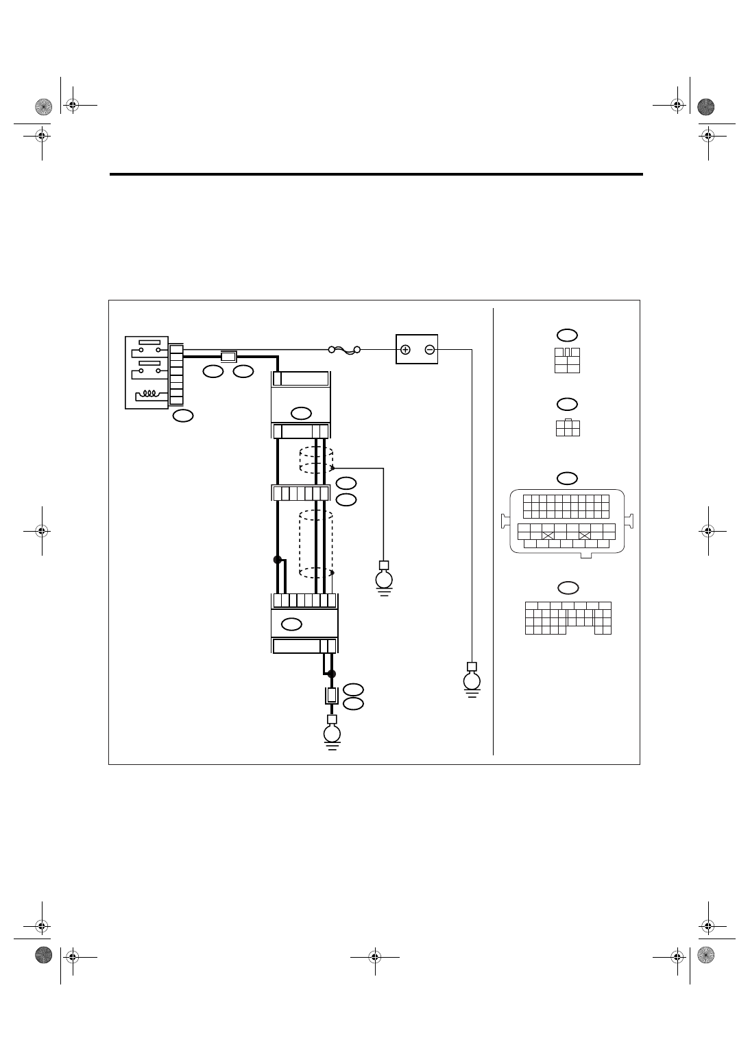
B: DTC P0031 HO2S HEATER CONTROL CIRCUIT LOW (BANK 1 SENSOR 1)
DTC DETECTING CONDITION:
Immediately at fault recognition
CAUTION:
After repair or replacement of faulty parts, conduct Clear Memory Mode <Ref. to EN(H4SO 2.5)(diag)-
40, Clear Memory Mode.> and Inspection Mode <Ref. to EN(H4SO 2.5)(diag)-33, Inspection Mode.>.
WIRING DIAGRAM:
• EC, EK, EH, ER and K4 model
• KA and KS model
NOTE:
Fuel injection system for KA and KS model is the same as 2.0 L model. Refer to EN(H4SO 2.0) section.
EN-03457
3
4
1
2
5
6
B327
SBF-5
E
E
B327
E24
6
4
5
3
2
1
25
33
26
3
2
6
7
52
B134
B21
E2
B21
E2
50
51
3
4
E2
B21
E
B21
1 2 3 4
12 13 14 15
5 6 7 8
16 17 18 19
9 10 11
20 21 22
23 24 25 26 27 28 29 30 31 32 33
35
34
37
36
39
38
41
40
43
42
44
45
47
46
49
48
51
50
53
52
54
E24
B134
5
6
7
8
2
1
9
4
3
10
24
22 23
25
11 12 13 14 15
26 27
28
16 17
18 19 20 21
33 34
29
32
30 31
ECM
BATTERY
FRONT OXYGEN
(A/F) SENSOR
OXYGEN (A/F)
SENSOR RELAY
1
3
4 5 6
2
3
4
1
6
Нет комментариевНе стесняйтесь поделиться с нами вашим ценным мнением.
Текст