Subaru Legacy (2005 year). Service manual — part 311
EN(H4DOTC)(diag)-13
ENGINE (DIAGNOSTICS)
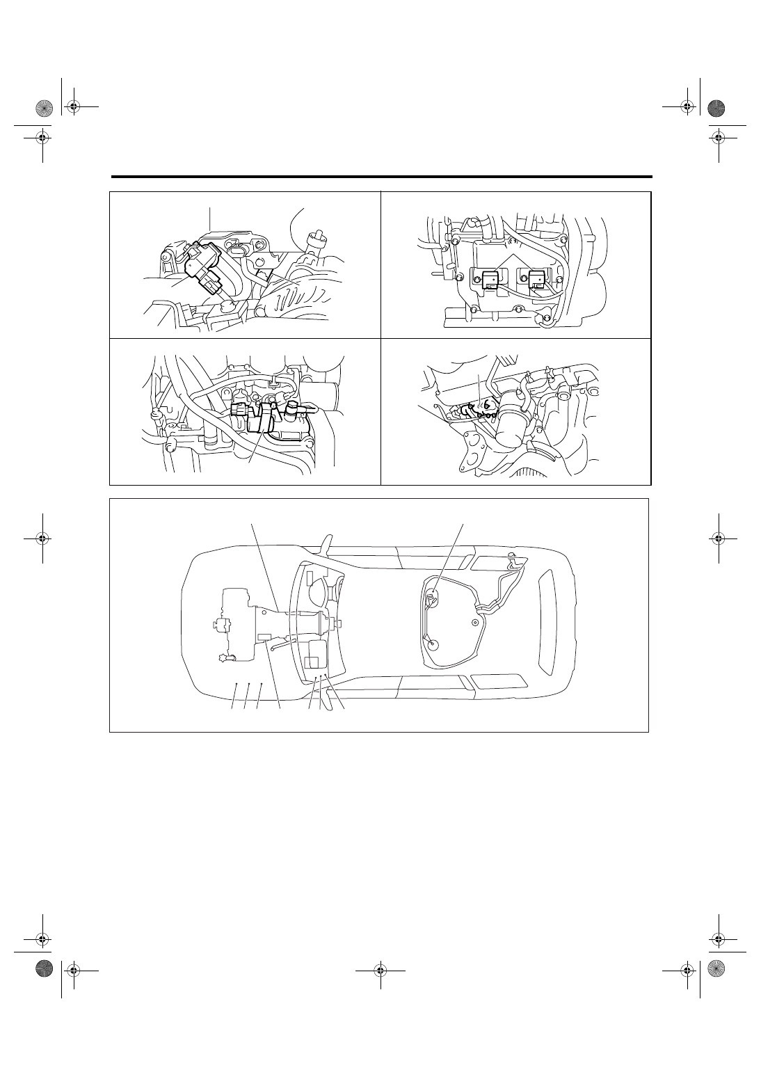
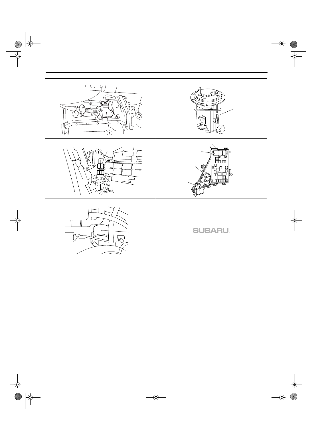
Electrical Component Location
(1)
Inhibitor switch
(4)
Fuel pump relay
(7)
Radiator sub fan relay
(2)
Fuel pump
(5)
Electronic throttle control relay
(8)
Radiator main fan relay 2
(3)
Main relay
(6)
Radiator main fan relay 1
(9)
Starter
EN-01935
(1)
(2)
EN-01936
(3)
EN-01937
(4)
EN-01938
(5)
EN-01898
(3)
(5)
(8) (7)
(2)
(6)
(9)
(4)
(1)
EN(H4DOTC)(diag)-14
ENGINE (DIAGNOSTICS)
Electrical Component Location
EN-00178
(2)
EN-02093
EN-02094
(3)
(4)
(5)
EN-02095
(8)
(7)
(6)
EN-02096
(9)
EN(H4DOTC)(diag)-15
ENGINE (DIAGNOSTICS)
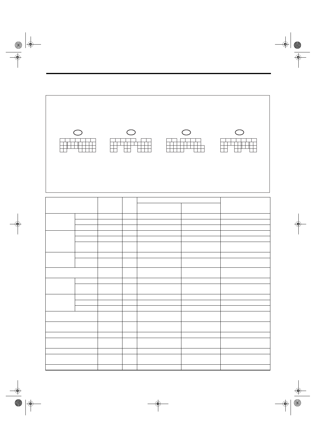
Engine Control Module (ECM) I/O Signal
5. Engine Control Module (ECM) I/O Signal
A: ELECTRICAL SPECIFICATION
DESCRIPTION
Connector
No.
Termi-
nal
No.
Signal (V)
Reference
Ignition SW ON
(engine OFF)
Engine ON
(idling)
Crankshaft
position sen-
sor
Signal (+)
B135
10
0
−7 — +7
Waveform
Signal (
−)
B135
22
0
0
—
Shield
B135
31
0
0
—
Rear oxygen
sensor
Signal
B137
25
0
0 — 0.9
—
Shield
B137
31
0
0
—
Ground
(sensor)
B136
35
0
0
—
Front oxygen
(A/F) sensor
heater
Signal 1
B134
3
—
—
Waveform
Signal 2
B134
2
—
—
Waveform
Rear oxygen sensor heater
signal
B135
2
0 — 13
—
Waveform
Engine cool-
ant tempera-
ture sensor
Signal
B136
14
1.0 — 1.4
1.0 — 1.4
After engine is warmed-up.
Ground
(sensor)
B136
35
0
0
After engine is warmed-up.
Air flow sensor
Signal
B136
23
—
0.3 — 4.5
—
Shield
B136
32
0
0
—
Ground
B136
31
0
0
—
Intake air temperature sen-
sor signal
B136
13
0.3 — 4.6
0.3 — 4.6
—
Wastegate control solenoid
valve
B134
32
0 or 10 — 13
0 or 13 — 14
Waveform
Starter switch
B137
8
0
0
Cranking: 8 —14
A/C switch
B137
17
ON: 10 — 13
OFF: 0
ON: 13 — 14
OFF: 0
—
Ignition switch
B137
14
10 — 13
13 — 14
—
Neutral position switch
B137
9
ON: 0
OFF: 10 —13
ON: 0
OFF: 13 —14
—
Test mode connector
B137
15
10 — 13
13 — 14
When connected: 0
EN-01812
B134
5
6
7
8
2
1
9
4
3
10
24
22
23
25
11
12
13
14
15
26
27
28
16
17
18
19
20
21
33
34
29
32
30
31
B136
5
6
7
8
2
1
9
4
3
10
24
22
23
25
11
12
13
14
15
26
27
28
16
17
18
19
20
21
33
34
29
32
30
31
35
B135
5
6
7
8
2
1
9
4
3
10
24
22
23
25
11
12
13
14
15
26
27
28
16
17
18
19
20
21
29
30
31
32
33
34
35
B137
5
6
7
8
2
1
9
4
3
10
22
23
11
12
13
14
15
24
25
26
16
17
18
19
20
21
27
28
29
30
31
To
To
To
To
EN(H4DOTC)(diag)-16
ENGINE (DIAGNOSTICS)
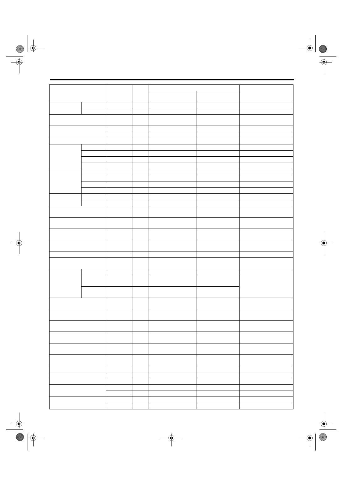
Engine Control Module (ECM) I/O Signal
Knock sensor
Signal
B136
25
2.8
2.8
—
Shield
B136
33
0
0
—
Backup power supply
B135
19
10 — 13
13 — 14
Ignition switch “OFF”: 10
— 13
Control module power sup-
ply
B135
5
10 — 13
13 — 14
—
B135
6
10 — 13
13 — 14
—
Sensor power supply
B136
16
5
5
—
Ignition control
#1
B135
18
0
13 — 14
Waveform
#2
B135
17
0
13 — 14
Waveform
#3
B135
16
0
13 — 14
Waveform
#4
B135
16
0
13 — 14
Waveform
Fuel injector
#1
B136
6
10 — 13
1 — 14
Waveform
#2
B136
5
10 — 13
1 — 14
Waveform
#3
B136
4
10 — 13
1 — 14
Waveform
#4
B136
3
10 — 13
1 — 14
Waveform
Fuel pump
control unit
Signal 1
B137
28
10 — 13
13 — 14
—
Signal 2
B135
27
0 or 5
0 or 5
Waveform
A/C relay control
B135
33
ON: 0.5 or less
OFF: 10 — 13
ON: 0.5 or less
OFF: 13 — 14
—
Radiator fan relay 1 control
B135
25
ON: 0.5 or less
OFF: 10 — 13
ON: 0.5 or less
OFF: 13 — 14
—
Radiator fan relay 2 control
B135
24
ON: 0.5 or less
OFF: 10 — 13
ON: 0.5 or less
OFF: 13 — 14
Model with A/C only
Malfunction indicator light
B134
17
—
—
Light ON: 1 or less
Light OFF: 10 — 14
Engine speed output
B134
23
—
0 — 13 or more
Waveform
Purge control solenoid valve
B134
14
ON: 1 or less
OFF: 10 — 13
ON: 1 or less
OFF: 13 — 14
Waveform
Manifold abso-
lute pressure
sensor
Signal
B136
22
1.7 — 2.4
1.1 — 1.6
—
Power
supply
B136
16
5
5
Ground
(sensor)
B136
35
0
0
Blower fan switch
B137
13
ON: 0
OFF: 10 — 13
ON: 0
OFF: 13 — 14
Model with manual A/C
only
Power steering oil pressure
switch
B137
10
10 — 13
ON: 0
OFF: 13 — 14
—
Front oxygen (A/F) sensor
signal (+)
B134
33
2.8 — 3.2
2.8 — 3.2
—
Front oxygen (A/F) sensor
signal (
−)
B134
26
2.4 — 2.7
2.4 — 2.7
—
Front oxygen (A/F) sensor
shield
B134
25
0
0
—
SSM communication line
B137
20
1 or less
←→ 4 or more
1 or less
←→ 4 or
more
—
GND (injector)
B137
7
0
0
—
GND (sensor)
B136
35
0
0
—
GND (ignition system)
B135
12
0
0
—
GND (power supply)
B135
4
0
0
—
B135
1
0
0
—
GND (control system)
B137
1
0
0
—
B137
2
0
0
—
DESCRIPTION
Connector
No.
Termi-
nal
No.
Signal (V)
Reference
Ignition SW ON
(engine OFF)
Engine ON
(idling)
Нет комментариевНе стесняйтесь поделиться с нами вашим ценным мнением.
Текст