Subaru Legacy (2005 year). Service manual — part 977
SL-31
SECURITY AND LOCKS
Rear Outer Handle
9. Rear Outer Handle
A: REMOVAL
1) Raise the rear door glass to the top position.
2) Remove the rear door trim. <Ref. to EI-48, RE-
MOVAL, Door Trim.>
3) Remove the sealing cover. <Ref. to EB-24, RE-
MOVAL, Rear Sealing Cover.>
4) Remove the rear door latch assembly. <Ref. to
SL-32, REMOVAL, Rear Door Latch and Door Lock
Actuator Assembly.>
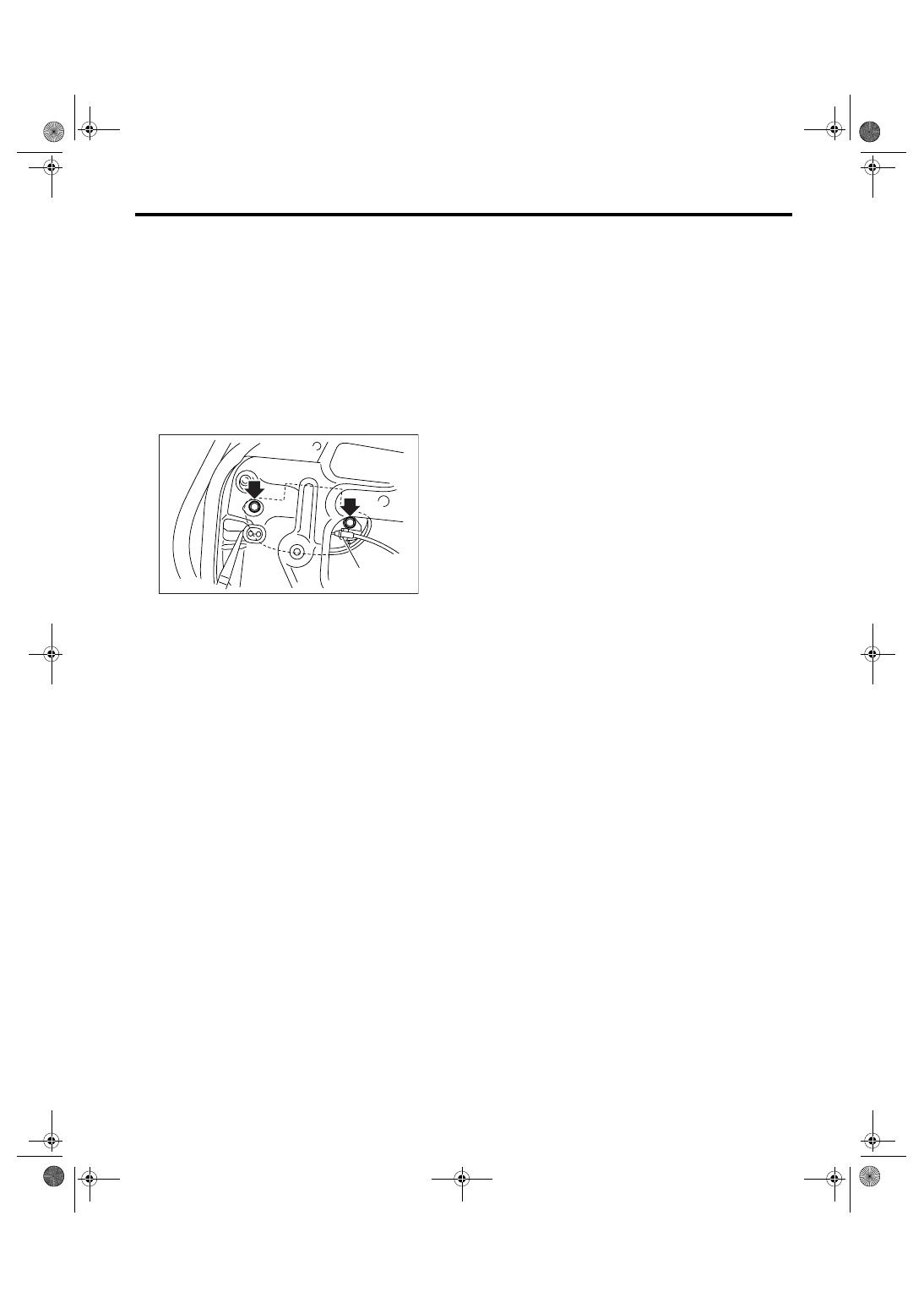
5) Remove the cable from cable clamp (1).
6) Remove the two bolts.
7) Detach the outer handle bracket. (Model with
double lock)
8) Detach the rear outer handle.
CAUTION:
Do not apply excessive force to remove the
handle from door panel. Otherwise door panel
may be deformed.
B: INSTALLATION
Install in the reverse order of removal.
NOTE:
Make sure the outer handle works correctly after in-
stallation.
C: INSPECTION
1) Check the cables for deformation. When it is de-
formed, straighten it because failure operations
may occur. When it is unrepairable, replace the
rear door latch & door lock actuator assembly.
2) Check the lever and wire for smooth operation.
SL-00284
(1)
SL-32
SECURITY AND LOCKS
Rear Door Latch and Door Lock Actuator Assembly
10.Rear Door Latch and Door
Lock Actuator Assembly
A: REMOVAL
1) Disconnect the ground cable from battery.
2) Remove the rear door trim. <Ref. to EI-48, RE-
MOVAL, Door Trim.>
3) Remove the wires from rear inner remote. <Ref.
to SL-30, REMOVAL, Rear Inner Remote.>
4) Remove the sealing cover. <Ref. to EB-24, RE-
MOVAL, Rear Sealing Cover.>
5) Remove the rear door glass. <Ref. to GW-24,
REMOVAL, Rear Door Glass.>
6) Remove the rear sash. <Ref. to GW-26, RE-
MOVAL, Rear Regulator and Motor Assembly.>
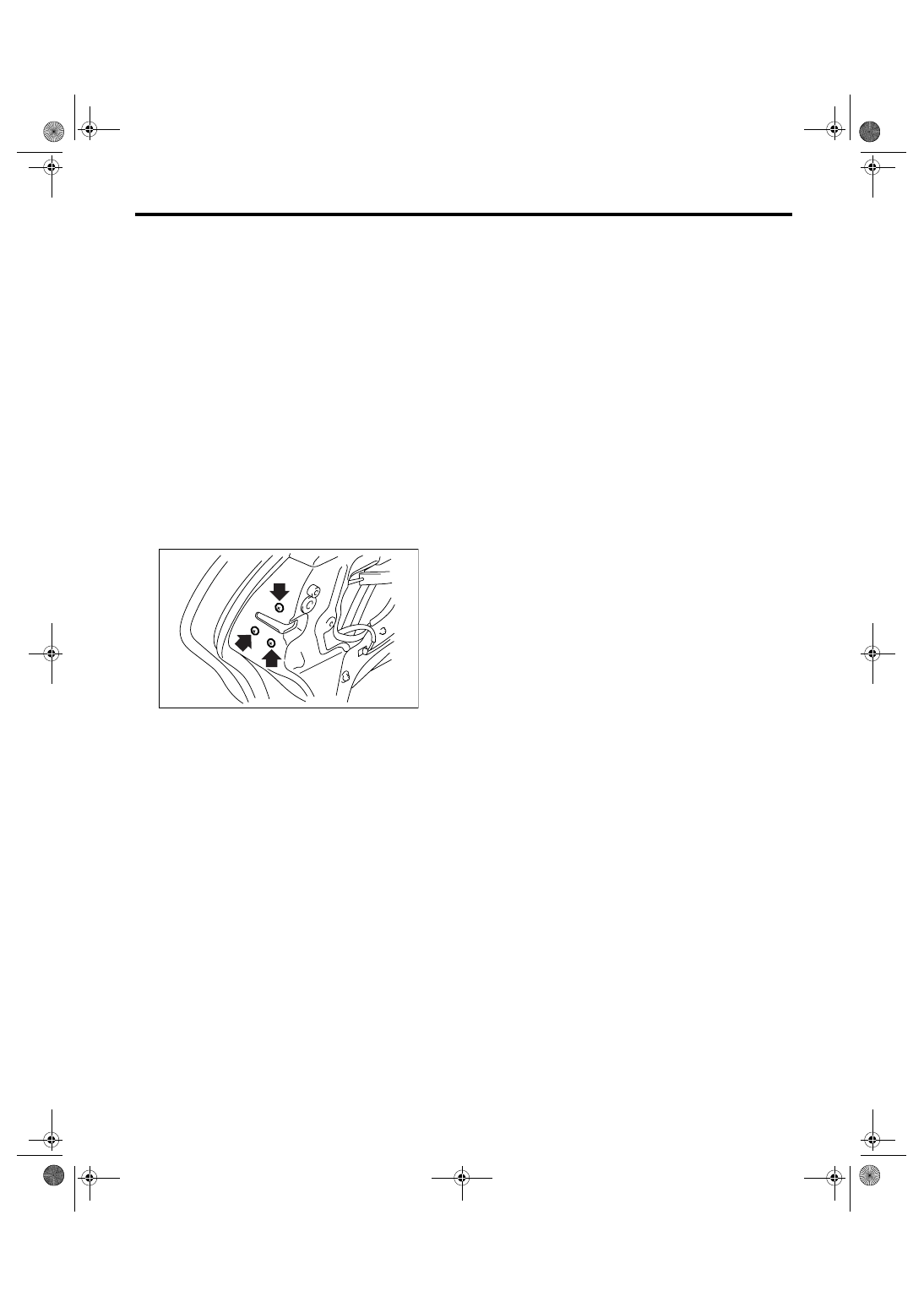
7) Take out the wire from wire clamp of outer han-
dle.
8) Detach the outer handle bracket. (Model with
double lock)
9) Remove the three screws.
10) Disconnect the connectors, and then remove
the rear door latch & door lock actuator assembly.
B: INSTALLATION
Install in the reverse order of removal.
NOTE:
Make sure the lock works correctly after installa-
tion.
C: INSPECTION
1) Check the cables for deformation. When it is de-
formed, straighten it because failure operations
may occur. When it is unrepairable, replace the
rear door latch & door lock actuator assembly.
2) Check the lever and wire for smooth operation.
SL-00285
SL-33
SECURITY AND LOCKS
Rear Door Lock Actuator
11.Rear Door Lock Actuator
A: REMOVAL
1) Remove the rear door latch & door lock actuator
assembly. <Ref. to SL-32, REMOVAL, Rear Door
Latch and Door Lock Actuator Assembly.>
2) Remove the pawl of rear door latch security cov-
er, and then remove the cover. (Model without dou-
ble lock)
3) Remove the screw from the rear door latch and
door lock actuator, and then remove the door lock
actuator. (Model without double lock)
B: INSTALLATION
Install in the reverse order of removal.
NOTE:
Make sure the lock works correctly after installa-
tion.
C: INSPECTION
1) Disconnect the door lock actuator harness con-
nector.
2) Connect the battery to door lock actuator termi-
nals.
If defective, replace the door lock actuator.
1. MODEL WITHOUT DOUBLE LOCK
2. MODEL WITH DOUBLE LOCK
• DOOR ACTUATOR RH
• DOOR ACTUATOR LH
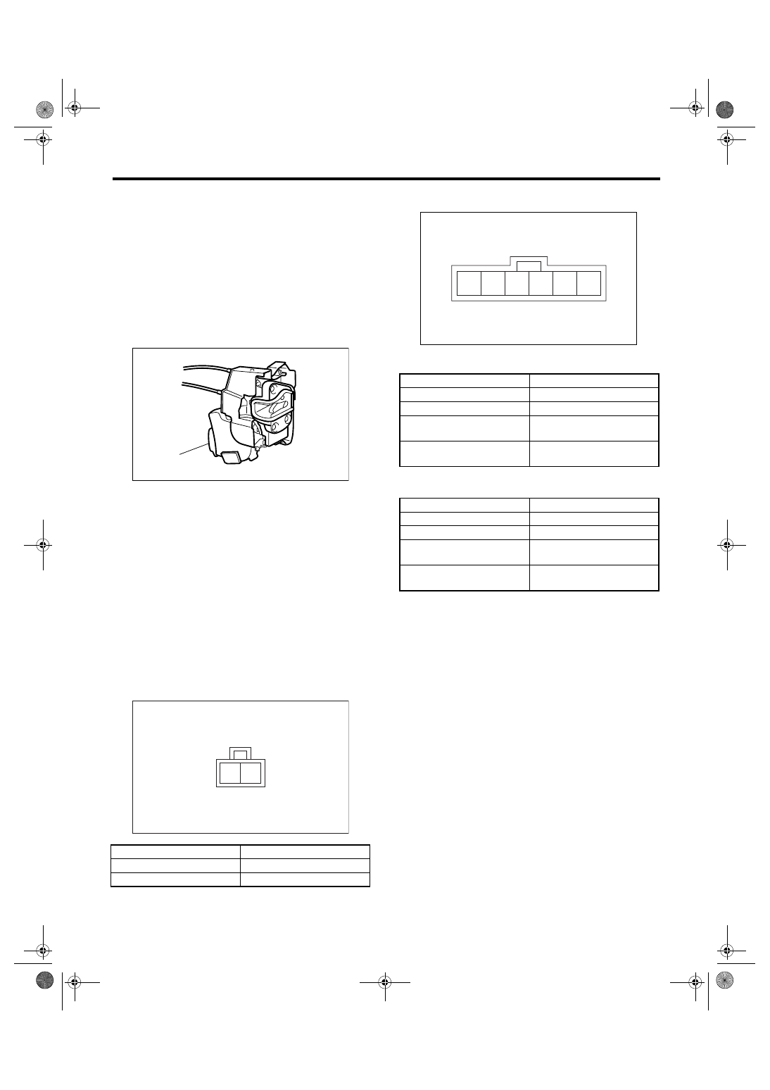
(1) Rear door lock actuator
Terminal No.
Actuator operation
No. 2 (+) and No. 1 (
−)
Unlocked
→ Locked
No. 1 (+) and No. 2 (
−)
Locked
→ Unlocked
SL-00282
(1)
SL-00235
2 1
Terminal No.
Actuator operation
No. 5 (+) and No. 1 (
−)
Unlocked
→ Locked
No. 1 (+) and No. 5 (
−)
Locked
→ Unlocked
No. 6 (+) and No. 1 (
−)
Double lock released
→
Double lock set
No. 1 (+) and No. 6 (
−)
Double lock set
→ Double
lock released
Terminal No.
Actuator operation
No. 2 (+) and No. 6 (
−)
Unlocked
→ Locked
No. 6 (+) and No. 2 (
−)
Locked
→ Unlocked
No. 1 (+) and No. 6 (
−)
Double lock released
→
Double lock set
No. 6 (+) and No. 1 (
−)
Double lock set
→ Double
lock released
SL-00283
6 5 4 3 2 1
SL-34
SECURITY AND LOCKS
Rear Gate Outer Handle
12.Rear Gate Outer Handle
A: REMOVAL
1) Remove the rear gate trim. <Ref. to EI-69, RE-
MOVAL, Rear Gate Trim.>
2) Remove the rear gate garnish. <Ref. to EI-76,
REMOVAL, Rear Gate Garnish.>
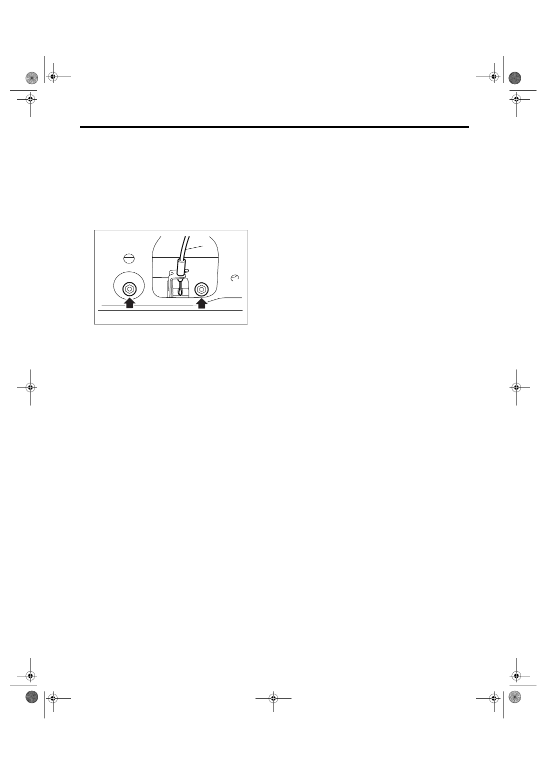
3) Remove the two nuts to take out the rear gate
outer handle.
4) Remove the cable of rear gate handle.
B: INSTALLATION
Install in the reverse order of removal.
NOTE:
Make sure the outer handle works correctly after in-
stallation.
C: INSPECTION
1) Check the cable of rear gate handle for deforma-
tion.
2) Check the rear gate outer handle and cable of
rear gate handle for smooth operation.
(1) Cable
SL-00239
(1)
Нет комментариевНе стесняйтесь поделиться с нами вашим ценным мнением.
Текст