Subaru Legacy (2005 year). Service manual — part 453
EN(H6DO)(diag)-125
ENGINE (DIAGNOSTICS)
Diagnostic Procedure with Diagnostic Trouble Code (DTC)
Y: DTC P0113 INTAKE AIR TEMPERATURE SENSOR 1 CIRCUIT HIGH
DTC DETECTING CONDITION:
Immediately at fault recognition
TROUBLE SYMPTOM:
• Erroneous idling
• Poor driving performance
CAUTION:
After repair or replacement of faulty parts, conduct Clear Memory Mode <Ref. to EN(H6DO)(diag)-41,
OPERATION, Clear Memory Mode.> and Inspection Mode <Ref. to EN(H6DO)(diag)-34, PROCEDURE,
Inspection Mode.>.
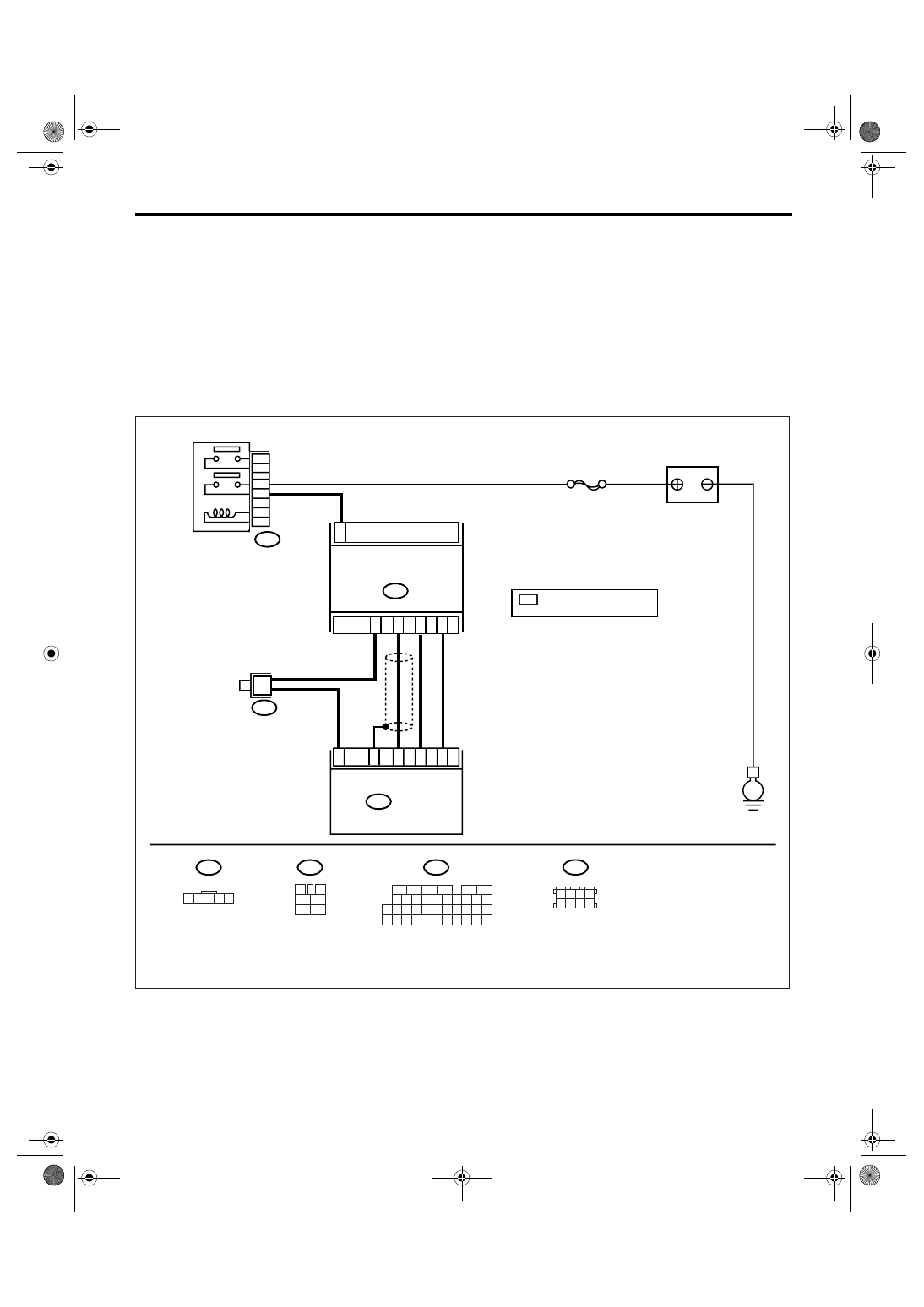
WIRING DIAGRAM:
EN-03496
B83
B3
BATTERY
E
B83
1
B3
MASS AIR FLOW AND INTAKE
AIR TEMPERATURE SENSOR
ECM
B136
SBF-7
1 2 3 4 5
3
4
1
2
5
6
B136
B47
*
*
2
4
3
5
31
13
23
35
32
MAIN RELAY
B47
1 2 3 4
5 6 7 8
5
6
7 8
2
1
9
4
3
10
24
22 23
25
11 12 13 14 15
26 27
28
16
17 18 19 20 21
33 34
29
32
30
31
35
6
4
: TERMINAL No.
RANDOM ARRANGEMENT
*
EN(H6DO)(diag)-126
ENGINE (DIAGNOSTICS)
Diagnostic Procedure with Diagnostic Trouble Code (DTC)
Step
Check
Yes
No
1
CHECK CURRENT DATA.
1) Start the engine.
2) Read the data of mass air flow and intake
air temperature sensor signal using Subaru
Select Monitor or general scan tool.
NOTE:
• Subaru Select Monitor
For detailed operation procedure, refer to
“READ CURRENT DATA FOR ENGINE”. <Ref.
to EN(H6DO)(diag)-26, Subaru Select Moni-
tor.>
• General scan tool
For detailed operation procedure, refer to the
general scan tool operation manual.
Is the intake air temperature
less than
−40°C (−40°F)?
Repair the poor
contact.
NOTE:
In this case, repair
the following:
• Poor contact in
mass air flow and
intake air tempera-
ture sensor
• Poor contact in
ECM
• Poor contact in
coupling connector
• Poor contact in
joint connector
2
CHECK HARNESS BETWEEN MASS AIR
FLOW AND INTAKE AIR TEMPERATURE
SENSOR AND ECM CONNECTOR.
1)Turn the ignition switch to OFF.
2)Disconnect the connector from mass air flow
and intake air temperature sensor.
3)Measure the voltage between mass air flow
and intake air temperature sensor connector
and engine ground.
Connector & terminal
(B3) No. 4 (+) — Engine ground (
−
):
Is the voltage more than 10 V? Repair battery
short circuit of har-
ness between
mass air flow and
intake air tempera-
ture sensor and
ECM connector.
3
CHECK HARNESS BETWEEN MASS AIR
FLOW AND INTAKE AIR TEMPERATURE
SENSOR AND ECM CONNECTOR.
1) Turn the ignition switch to ON.
2) Measure the voltage between mass air flow
and intake air temperature sensor connector
and engine ground.
Connector & terminal
(B3) No. 4 (+) — Engine ground (
−
):
Is the voltage more than 10 V? Repair battery
short circuit of har-
ness between
mass air flow and
intake air tempera-
ture sensor and
ECM connector.
4
CHECK HARNESS BETWEEN MASS AIR
FLOW AND INTAKE AIR TEMPERATURE
SENSOR AND ECM CONNECTOR.
Measure the voltage between mass air flow
and intake air temperature sensor connector
and engine ground.
Connector & terminal
(B3) No. 4 (+) — Engine ground (
−
):
Is the voltage more than 3 V?
Repair the har-
ness and connec-
tor.
NOTE:
In this case, repair
the following:
• Open circuit of
harness between
mass air flow and
intake air tempera-
ture sensor and
ECM connector
• Poor contact in
mass air flow and
intake air tempera-
ture sensor
• Poor contact in
ECM
• Poor contact in
coupling connector
• Poor contact in
joint connector
EN(H6DO)(diag)-127
ENGINE (DIAGNOSTICS)
Diagnostic Procedure with Diagnostic Trouble Code (DTC)
5
CHECK HARNESS BETWEEN MASS AIR
FLOW AND INTAKE AIR TEMPERATURE
SENSOR AND ECM CONNECTOR.
1) Turn the ignition switch to OFF.
2) Measure the resistance of harness
between mass air flow and intake air tempera-
ture sensor connector and engine ground.
Connector & terminal
(B3) No. 5 — Engine ground:
Is the resistance less than 5
Ω?
Replace the mass
air flow and intake
air temperature
sensor. <Ref. to
FU(H6DO)-24,
Mass Air Flow and
Intake Air Temper-
ature Sensor.>
Repair the har-
ness and connec-
tor.
NOTE:
In this case, repair
the following:
• Open circuit of
harness between
mass air flow and
intake air tempera-
ture sensor and
ECM connector
• Poor contact in
mass air flow and
intake air tempera-
ture sensor
• Poor contact in
ECM
• Poor contact in
joint connector
Step
Check
Yes
No
EN(H6DO)(diag)-128
ENGINE (DIAGNOSTICS)
Diagnostic Procedure with Diagnostic Trouble Code (DTC)
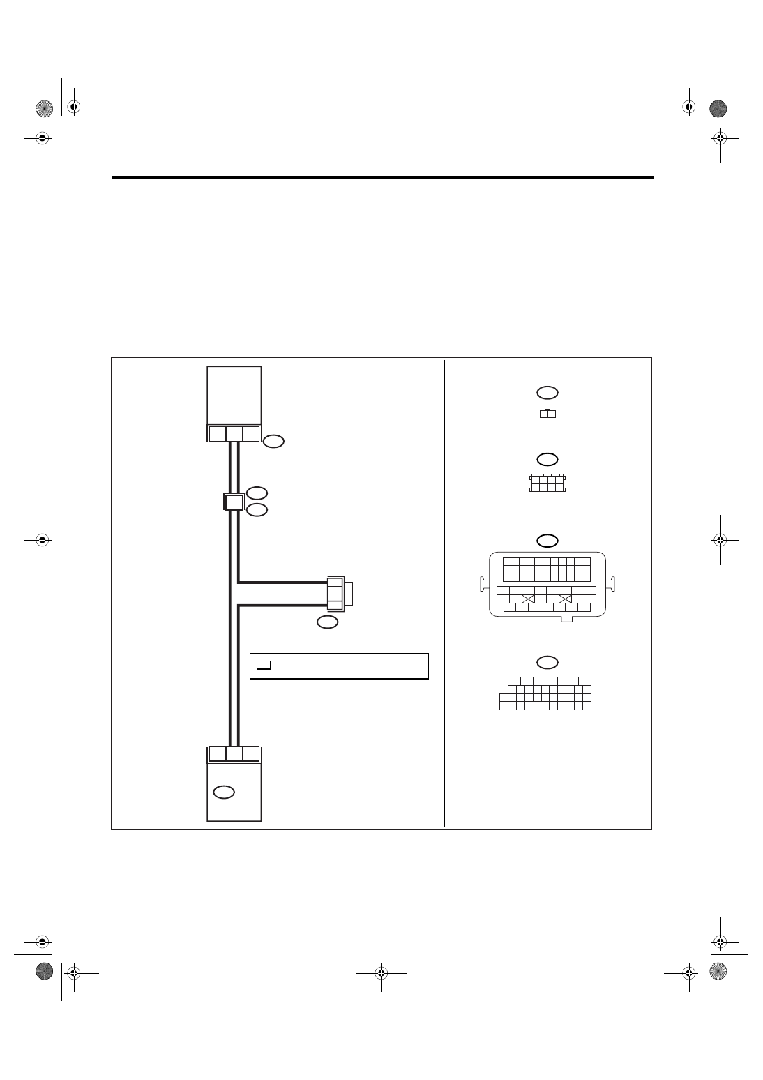
Z: DTC P0117 ENGINE COOLANT TEMPERATURE CIRCUIT LOW
DTC DETECTING CONDITION:
Immediately at fault recognition
TROUBLE SYMPTOM:
• Hard to start
• Erroneous idling
• Poor driving performance
CAUTION:
After repair or replacement of faulty parts, conduct Clear Memory Mode <Ref. to EN(H6DO)(diag)-41,
OPERATION, Clear Memory Mode.> and Inspection Mode <Ref. to EN(H6DO)(diag)-34, PROCEDURE,
Inspection Mode.>.
WIRING DIAGRAM:
EN-03498
*
*
B83
35
14
19
8
B136
ECM
1
2
E2
B21
E8
ENGINE
COOLANT
TEMPERATURE
SENSOR
E8
B21
1 2 3 4
5 6 7 8
B83
1 2 3 4
12 13 14 15
5 6 7 8
16 17 18 19
9 10 11
20 21 22
23 24 25 26 27 28 29 30 31 32 33
35
34
37
36
39
38
41
40
43
42
44
45
47
46
49
48
51
50
53
52
54
B136
5
6
7 8
2
1
9
4
3
10
24
22 23
25
11 12 13 14 15
26 27
28
16
17 18 19 20 21
33 34
29
32
30
31
35
*
: TERMINAL No. RANDOM ARRANGEMENT
1 2
Нет комментариевНе стесняйтесь поделиться с нами вашим ценным мнением.
Текст