Subaru Legacy (2005 year). Service manual — part 505
AUTOMATIC TRANSMISSION
4AT
Page
General Description . . . . . . . . . . . . . . . . . . . . . 2
Automatic Transmission Fluid . . . . . . . . . . . . . . . . ...31
Differential Gear Oil. . . . . . . . . . . . . . . . . . . . ...33
Road Test. . . . . . . . . . . . . . . . . . . . . . . . ..34
Stall Test . . . . . . . . . . . . . . . . . . . . . . . . ...35
Time Lag Test . . . . . . . . . . . . . . . . . . . . . . ...36
Line Pressure Test . . . . . . . . . . . . . . . . . . . . . 37
Transfer Clutch Pressure Test . . . . . . . . . . . . . . . . ..38
Automatic Transmission Assembly . . . . . . . . . . . . . . ...39
Transmission Mounting System . . . . . . . . . . . . . . . . 47
Extension Case Oil Seal . . . . . . . . . . . . . . . . . . ...49
Differential Side Retainer Oil Seal. . . . . . . . . . . . . . . .50
Inhibitor Switch. . . . . . . . . . . . . . . . . . . . . . ..51
Front Vehicle Speed Sensor . . . . . . . . . . . . . . . . . .55
Rear Vehicle Speed Sensor. . . . . . . . . . . . . . . . . ..58
Torque Converter Turbine Speed Sensor . . . . . . . . . . . . .59
Control Valve Strainer . . . . . . . . . . . . . . . . . . . ...60
Control Valve Body . . . . . . . . . . . . . . . . . . . . ...62
Air Bleeding of Control Valve . . . . . . . . . . . . . . . . . 64
ATF Filter . . . . . . . . . . . . . . . . . . . . . . . . ..65
Transmission Control Module (TCM) . . . . . . . . . . . . . . 66
Lateral G Sensor . . . . . . . . . . . . . . . . . . . . . ...67
ATF Cooler Pipe and Hose . . . . . . . . . . . . . . . . . ...68
ATF Cooler (with Warmer Function) . . . . . . . . . . . . . . .73
Warmer Cock . . . . . . . . . . . . . . . . . . . . . . . 77
Air Breather Hose. . . . . . . . . . . . . . . . . . . . . ..79
Oil Charge Pipe. . . . . . . . . . . . . . . . . . . . . . .80
Torque Converter Clutch Assembly . . . . . . . . . . . . . . ..81
Extension Case . . . . . . . . . . . . . . . . . . . . . . .83
Transfer Clutch. . . . . . . . . . . . . . . . . . . . . . ..87
Multi-plate Clutch . . . . . . . . . . . . . . . . . . . . . ..93
Rear Drive Shaft. . . . . . . . . . . . . . . . . . . . . . 94
Reduction Driven Gear. . . . . . . . . . . . . . . . . . . ..95
Reduction Drive Gear. . . . . . . . . . . . . . . . . . . . 97
Center Differential Carrier . . . . . . . . . . . . . . . . . . .99
Parking Pawl . . . . . . . . . . . . . . . . . . . . . . ...101
Converter Case . . . . . . . . . . . . . . . . . . . . . ...102
Oil Pump Housing . . . . . . . . . . . . . . . . . . . . ...104
Drive Pinion Shaft Assembly. . . . . . . . . . . . . . . . ...109
Front Differential Assembly . . . . . . . . . . . . . . . . . .115
AT Main Case . . . . . . . . . . . . . . . . . . . . . . .121
Transmission Control Device . . . . . . . . . . . . . . . . ..142
4AT-2
AUTOMATIC TRANSMISSION
General Description
1. General Description
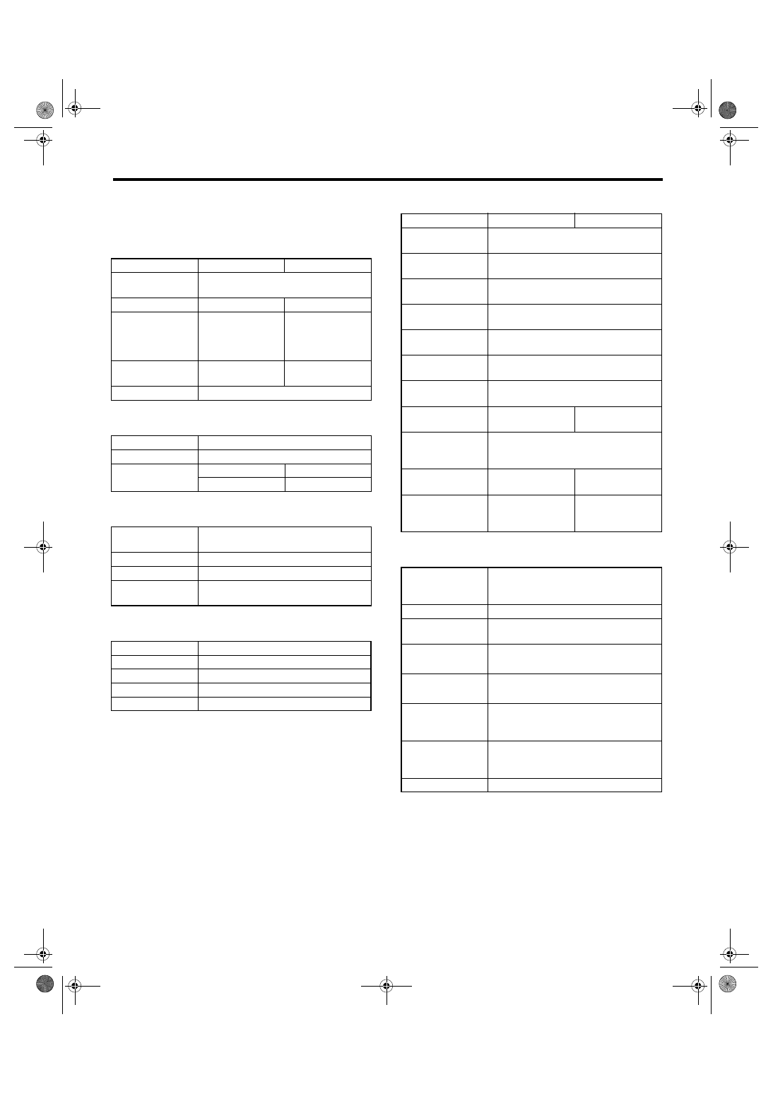
A: SPECIFICATION
1. TORQUE CONVERTER CLUTCH
2. OIL PUMP
3. TRANSMISSION CONTROL ELEMENT
4. TRANSMISSION GEAR RATIO
5. PLANETARY GEAR AND PLATE
6. SELECTOR POSITION
Model
2.0 L
2.5 L
Type
Symmetric, 3 element, single stage,
2 phase torque converter
Stall torque ratio
2.0 — 2.2
1.8 — 2.15
Nomi-
nal
diame-
ter
mm (in)
236 (9.29)
246 (9.69)
Stall speed (at sea
level)
2,000 — 2,500
rpm
2,300 — 2,800
rpm
One-way clutch
Sprague type one-way clutch
Type
Parachoid constant-discharge pump
Driving method
Driven by engine
Number of teeth
Inner rotor
9
Outer rotor
10
Type
4-forward, 1-reverse,
double-row planetary gears
Multi-plate clutch
3 sets
Multi-plate brake
2 sets
One-way clutch
(sprague type)
1 sets
1st
2.785
2nd
1.545
3rd
1.000
4th
0.694
Rev
2.272
Model
2.0 L
2.5 L
Front sun gear
number of teeth
33
Front pinion num-
ber of teeth
21
Front internal gear
number of teeth
75
Rear sun gear
number of teeth
42
Rear pinion num-
ber of teeth
17
Rear internal gear
number of teeth
75
Drive plate num-
ber of high clutch
4
Drive plate num-
ber of low clutch
4
5
Drive plate num-
ber of reverse
clutch
2
Drive plate num-
ber of 2-4 brake
2
3
Drive plate num-
ber of low &
reverse brake
4
5
P (Park)
Transmission in neutral, output mem-
ber immovable, and engine start possi-
ble
R (Reverse)
Transmission in reverse for backing
N (Neutral)
Transmission in neutral and engine
start possible
D (Drive)
4-forward automatic gear change
1st
←
→
2nd
←
→
3rd
←
→
4th
SPORT mode
4-forward automatic gear change
1st
←
→
2nd
←
→
3rd
←
→
4th
Manual mode (+)
4-forward manual gear change
(shift up)
1st
→ 2nd → 3rd → 4th
Manual mode (
−)
4-forward manual gear change
(shift down)
1st
← 2nd ← 3rd ← 4th
Control method
Wire cable type
4AT-3
AUTOMATIC TRANSMISSION
General Description
7. HYDRAULIC CONTROL AND LUBRICA-
TION
8. COOLING AND HARNESS
9. TRANSFER
10.FINAL REDUCTION
11.RECOMMENDED GEAR OIL
Type
Electronic hydraulic control
[Four forward speed
changes by electrical signals
of vehicle speed and accel-
erator (throttle) opening]
Fluid
SUBARU ATF or IDEMITSU
“Apolloil ATF HP”, Castrol
“Transmax J”
NOTE:
If the ATF above are not
available, use Dexron III.
Fluid
capacity
2 (US
qt, Imp
qt)
2.0 L
8.4 — 8.7
(8.9 — 9.2, 7.4 — 7.7)
2.5 L
9.3 — 9.6
(9.8 — 10.1, 8.2 — 8.4)
Lubrication system
Forced feed lubrication with
oil pump
Oil
Automatic transmission fluid
(above mentioned)
Cooling system
Liquid-cooled cooler
Inhibitor switch
12 poles
Transmission harness
20 poles
Model
2.0 L
2.5 L
except for
VTD model
2.5 L VTD
model
Transfer type
Multi-plate transfer
(MP-T)
Variable
torque dis-
tribution
(VTD)
Drive & driven
plate number of
transfer clutch
4
5
3
Control method
Electronic hydraulic type
Lubricant
The same Automatic transmission fluid
used in automatic transmission
Reduction gear
ratio
1.000 (53/53)
Model
Except for OUTBACK
OUTBACK
Front final reduction gear ratio
4.111 (37/9)
4.444 (40/9)
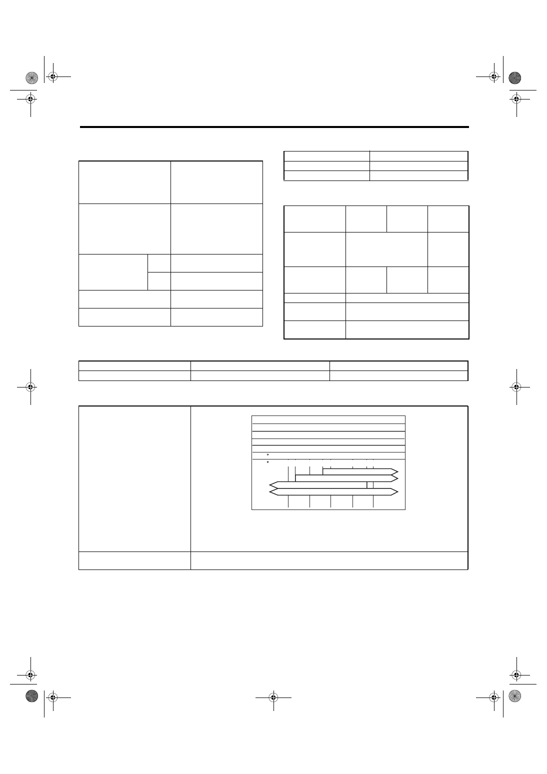
Lubrication oil
(1) Item
(3) API standard
(2) Front differential gear oil
(4) SAE viscosity No. and applica-
ble temperature
Front differential oil
capacity
2 (US qt,
Imp qt)
1.1 — 1.3 (1.2 — 1.4, 1.0 — 1.1)
MT-00001
(1)
(4)
GL-5
(3)
(2)
( C)
( F)
-30 -26 -15
15
90
85W
80W
75W -90
25
30
-5 0
-22 -15
23 32
86
59
77
5
4AT-4
AUTOMATIC TRANSMISSION
General Description
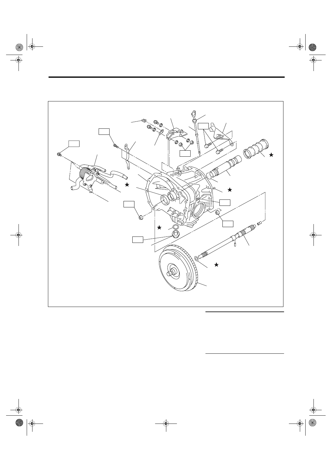
B: COMPONENT
1. TORQUE CONVERTER CLUTCH AND CASE
(1)
Pitching stopper bracket
(11)
Torque converter clutch ASSY
Tightening torque: N
⋅
m (kgf-m, ft-lb)
(2)
O-ring
(12)
Drain plug
T1: 18 (1.8, 13.3)
(3)
Differential oil level gauge
(13)
Gasket
T2: 23 (2.3, 17)
(4)
Stay
(14)
Oil seal
T3: 33 (3.4, 24.3)
(5)
Seal pipe
(15)
Converter case
T4: 41 (4.2, 30.4)
(6)
Oil pump shaft
(16)
Harness stay
T5: 44 (4.5, 32.5) (Aluminum gasket)
70 (7.1, 51.6) (Copper gasket)
(7)
Clip
(17)
ATF cooler ASSY with warmer
function (if equipped)
(8)
Oil drain pipe
(9)
Input shaft
(18)
Bracket (if equipped)
(10)
O-ring
(19)
Clip (if equipped)
AT-02159
T4
T4
T4
T4
T5
T1
(8)
(11)
(1)
(2)
(16)
(18)
(17)
(19)
(3)
(4)
(7)
(5)
(6)
(10)
(9)
(14)
(15)
(12)
(13)
T3
T2
Нет комментариевНе стесняйтесь поделиться с нами вашим ценным мнением.
Текст