Subaru Legacy (2005 year). Service manual — part 187
EN(H4SO 2.5)(diag)-33
ENGINE (DIAGNOSTICS)
Inspection Mode
11.Inspection Mode
A: PROCEDURE
Perform the diagnosis shown in the following DTC table.
When performing the diagnosis not listed in “List of Diagnostic Trouble Code (DTC)”, refer the item on the
drive cycle. <Ref. to EN(H4SO 2.5)(diag)-38, Drive Cycle.>
NOTE:
KA and KS model is the same as 2.0 L model. Refer to EN(H4SO 2.0) section.
DTC
Item
Condition
P0031
HO2S Heater Control Circuit Low (Bank 1 Sensor 1)
—
P0032
HO2S Heater Control Circuit High (Bank 1 Sensor 1)
—
P0037
HO2S Heater Control Circuit Low (Bank 1 Sensor 2)
—
P0038
HO2S Heater Control Circuit High (Bank 1 Sensor 2)
—
P0102
Mass or Volume Air Flow Circuit Low Input
—
P0103
Mass or Volume Air Flow Circuit High Input
—
P0107
Manifold Absolute Pressure/Barometric Pressure Circuit Low Input
—
P0108
Manifold Absolute Pressure/Barometric Pressure Circuit High Input
—
P0112
Intake Air Temperature Sensor 1 Circuit Low
—
P0113
Intake Air Temperature Sensor 1 Circuit High
—
P0117
Engine Coolant Temperature Circuit Low
—
P0118
Engine Coolant Temperature Circuit High
—
P0122
Throttle/Pedal Position Sensor/Switch “A” Circuit Low
—
P0123
Throttle/Pedal Position Sensor/Switch “A” Circuit High
—
P0131
O2 Sensor Circuit Low Voltage (Bank 1 Sensor 1)
—
P0132
O2 Sensor Circuit High Voltage (Bank 1 Sensor 1)
—
P0134
O2 Sensor Circuit No Activity Detected (Bank 1 Sensor 1)
—
P0137
O2 Sensor Circuit Low Voltage (Bank 1 Sensor 2)
—
P0138
O2 Sensor Circuit High Voltage (Bank 1 Sensor 2)
—
P0171
System Too Lean (Bank 1)
—
P0172
System Too Rich (Bank 1)
—
P0222
Throttle/Pedal Position Sensor/Switch “B” Circuit Low
—
P0223
Throttle/Pedal Position Sensor/Switch “B” Circuit High
—
P0327
Knock Sensor 1 Circuit Low (Bank 1 or Single Sensor)
—
P0328
Knock Sensor 1 Circuit High (Bank 1 or Single Sensor)
—
P0335
Crankshaft Position Sensor “A” Circuit
—
P0340
Camshaft Position Sensor “A” Circuit (Bank 1 or Single Sensor)
—
P0400
Exhaust gas recirculation flow
—
P0458
Evaporative Emission System Purge Control Valve Circuit Low
—
P0462
Fuel Level Sensor “A” Circuit Low
—
P0463
Fuel Level Sensor “A” Circuit High
—
P0500
Vehicle Speed Sensor “A”
—
P0512
Starter Request Circuit
—
P0513
Incorrect Immobilizer Key
—
P0519
Idle Air Control System performance
—
P0600
Serial Communication Link
—
P0604
Internal Control Module Random Access Memory (RAM) Error
—
P0605
Internal Control Module Read Only Memory (ROM) Error
—
P0607
Control Module Performance
—
P0638
Throttle Actuator Control Range/Performance (Bank 1)
—
P0691
Fan 1 Control Circuit Low
—
P0692
Fan 1 Control Circuit High
—
P0851
Park/Neutral Position Switch Input Circuit Low
—
EN(H4SO 2.5)(diag)-34
ENGINE (DIAGNOSTICS)
Inspection Mode
P0852
Park/Neutral Position Switch Input Circuit High
—
P1152
O2 Sensor Circuit Range/Performance (Low) (Bank1 Sensor1)
—
P1153
O2 Sensor Circuit Range/Performance (High) (Bank1 Sensor1)
—
P1160
Return Spring Failure
—
P1492
EGR Solenoid Valve Signal #1 Circuit Malfunction (Low Input)
—
P1493
EGR Solenoid Valve Signal #1 Circuit Malfunction (High Input)
—
P1494
EGR Solenoid Valve Signal #2 Circuit Malfunction (Low Input)
—
P1495
EGR Solenoid Valve Signal #2 Circuit Malfunction (High Input)
—
P1496
EGR Solenoid Valve Signal #3 Circuit Malfunction (Low Input)
—
P1497
EGR Solenoid Valve Signal #3 Circuit Malfunction (High Input)
—
P1498
EGR Solenoid Valve Signal #4 Circuit Malfunction (Low Input)
—
P1499
EGR Solenoid Valve Signal #4 Circuit Malfunction (High Input)
—
P1518
Starter Switch Circuit Low Input
—
P1560
Back-up Voltage Circuit Malfunction
—
P1570
Antenna
—
P1571
Reference Code Incompatibility
—
P1572
IMM Circuit Failure
—
P1574
Key Communication Failure
—
P1576
EGI Control Module EEPROM
—
P1577
IMM Control Module EEPROM
—
P1578
Meter Failure
—
P2004
Intake Manifold Runner Control Stuck Open (Bank 1)
Engine coolant temperature at
engine start is
−5 — 5°C (−41 —
41
°F)
P2005
Intake Manifold Runner Control Stuck Open (Bank 2)
Engine coolant temperature at
engine start is
−5 — 5°C (−41 —
41
°F)
P2006
Intake Manifold Runner Control Stuck Closed (Bank 1)
—
P2007
Intake Manifold Runner Control Stuck Closed (Bank 2)
—
P2008
Intake Manifold Runner Control Circuit / Open (Bank 1)
—
P2009
Intake Manifold Runner Control Circuit Low (Bank 1)
—
P2011
Intake Manifold Runner Control Circuit / Open (Bank 2)
—
P2012
Intake Manifold Runner Control Circuit Low (Bank 2)
—
P2016
Intake Manifold Runner Position Sensor / Switch Circuit Low (Bank 1)
—
P2017
Intake Manifold Runner Position Sensor / Switch Circuit High (Bank 1)
—
P2021
Intake Manifold Runner Position Sensor / Switch Circuit Low (Bank 2)
—
P2022
Intake Manifold Runner Position Sensor / Switch Circuit High (Bank 2)
—
P2101
Throttle Actuator Control Motor Circuit Range/Performance
—
P2102
Throttle Actuator Control Motor Circuit Low
—
P2103
Throttle Actuator Control Motor Circuit High
—
P2109
Throttle/Pedal Position Sensor A Minimum Stop Performance
—
P2122
Throttle/Pedal Position Sensor/Switch “D” Circuit Low Input
—
P2123
Throttle/Pedal Position Sensor/Switch “D” Circuit High Input
—
P2127
Throttle/Pedal Position Sensor/Switch “E” Circuit Low Input
—
P2128
Throttle/Pedal Position Sensor/Switch “E” Circuit High Input
—
P2135
Throttle/Pedal Position Sensor/Switch “A”/“B” Voltage Correlation
—
P2138
Throttle/Pedal Position Sensor/Switch “D”/“E” Voltage Correlation
—
P2503
Charging System Voltage Low
—
DTC
Item
Condition
EN(H4SO 2.5)(diag)-35
ENGINE (DIAGNOSTICS)
Inspection Mode
1. PREPARATION FOR THE INSPECTION
MODE
1) Check that the battery voltage is more than 12 V
and fuel remains half [20 — 40
2 (5.3 — 10.6 US
gal, 4.4 — 8.8 Imp gal)].
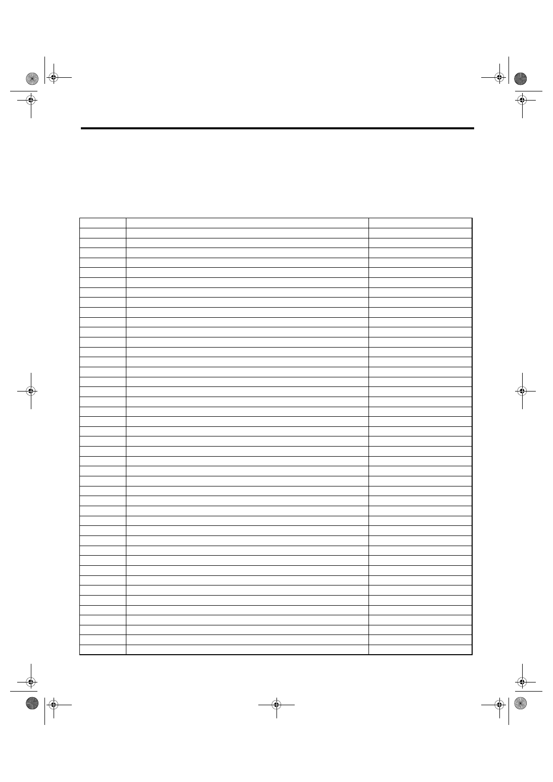
2) Lift-up the vehicle using a garage jack and place
it on rigid racks, or drive the vehicle onto free roll-
ers.
WARNING:
• Before lifting-up the vehicle, ensure parking
brakes are applied.
• Do not use a pantograph jack in place of a rig-
id rack.
• Secure a rope or wire to the front or rear tow-
ing hooks to prevent the lateral runout of front
wheels.
• Do not abruptly depress/release clutch pedal
or accelerator pedal during works even when
the engine is operating at low speeds since this
may cause vehicle to jump off free rollers.
• In order to prevent the vehicle from slipping
due to vibration, do not place any wooden
blocks or similar items between the rigid racks
and vehicle.
• Since the rear wheels will also rotate, do not
place anything near them. Also, make sure that
nobody goes in front of the vehicle.
2. SUBARU SELECT MONITOR
1) After clearing the memory, check for any remain-
ing unresolved trouble data. <Ref. to EN(H4SO
2.5)(diag)-40, Clear Memory Mode.>
2) Idle the engine.
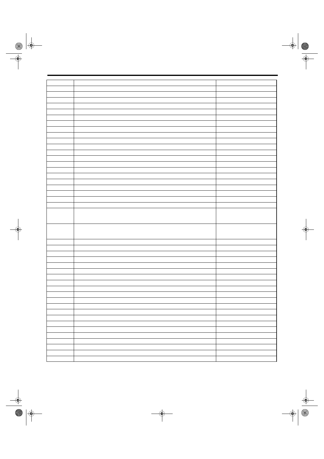
3) Prepare the Subaru Select Monitor kit. <Ref. to
EN(H4SO 2.5)(diag)-7, PREPARATION TOOL,
General Description.>
4) Connect the diagnosis cable to Subaru Select
Monitor.
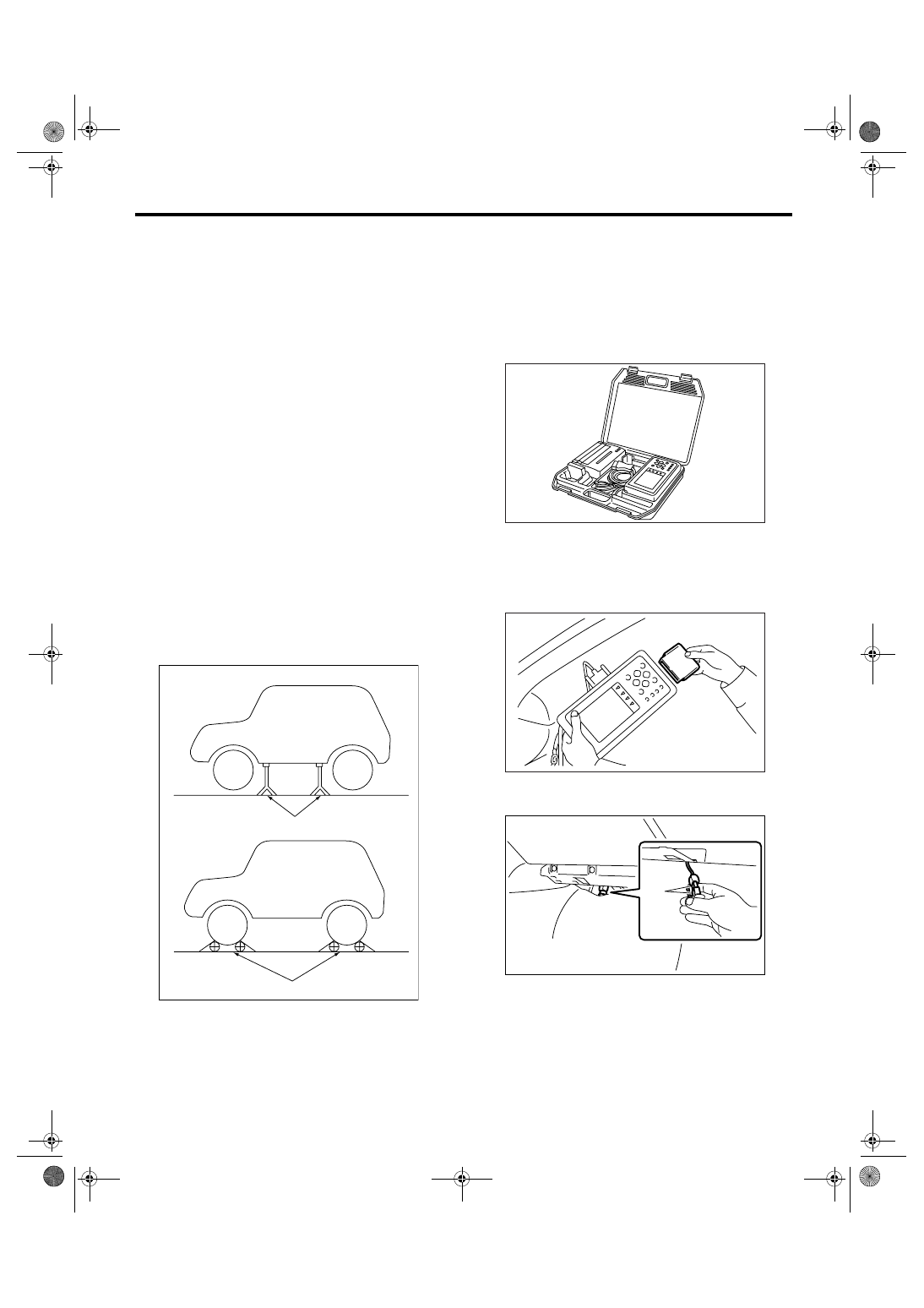
5) Insert the cartridge to Subaru Select Monitor.
<Ref. to EN(H4SO 2.5)(diag)-7, PREPARATION
TOOL, General Description.>
6) Connect the test mode connector (A) located at
the lower portion of glove box.
(A) Rigid racks
(B) Free rollers
EN-00041
(A)
(B)
EN-00038
EN-00039
PI-00201
(A)

EN(H4SO 2.5)(diag)-36
ENGINE (DIAGNOSTICS)
Inspection Mode
7) Connect the Subaru Select Monitor to data link
connector located in the lower portion of the instru-
ment panel (on the driver’s side).
CAUTION:
Do not connect any scan tools except Subaru
Select Monitor or general scan tool.
8) Turn the ignition switch to ON (engine OFF), and
the Subaru Select Monitor power switch to ON.
9) On the «Main Menu» display screen, select the
{Each System Check} and press the [YES] key.
10) On the «System Selection Menu» display
screen, select the {Engine} and press the [YES]
key.
11) Press the [YES] key after the information of en-
gine type has been displayed.
12) On the «Engine Diagnosis» screen, select the
{D Check} and press the [YES] key.
13) When the “Perform D Check?” is shown on the
screen, press the [YES] key.
14) Perform subsequent procedures as instructed
on the display screen.
• If trouble still remains in the memory, the corre-
sponding DTC appears on the display screen.
NOTE:
• For detailed operation procedure, refer to the
SUBARU SELECT MONITOR OPERATION MAN-
UAL.
• For details concerning DTC, refer to “List of Diag-
nostic Trouble Code (DTC)”.
<Ref. to EN(H4SO 2.5)(diag)-69, List of Diagnostic
Trouble Code (DTC).>
• Release the parking brake.
• The speed difference between front and rear
wheels may light the ABS warning light, but this in-
dicates no malfunctions. When engine control diag-
nosis is finished, perform the ABS memory
clearance procedure of self-diagnosis function.
3. GENERAL SCAN TOOL
1) After performing the diagnostics and clearing the
memory, check for any remaining unresolved trou-
ble data. <Ref. to EN(H4SO 2.5)(diag)-40, Clear
Memory Mode.>
2) Idle the engine.
3) Connect the test mode connector (A) located at
the lower portion of glove box.
4) Connect the general scan tool to data link con-
nector located in the lower portion of the instrument
panel (on the driver’s side).
CAUTION:
Do not connect any scan tools except Subaru
Select Monitor or general scan tool.
5) Start the engine.
NOTE:
• Ensure the select lever is placed in “P” position
before starting. (AT model)
• Depress the clutch pedal when starting the en-
gine. (MT model)
6) Using the select lever or shift lever, turn the “P”
position switch and the “N” position switch to ON.
7) Depress the brake pedal to turn brake switch
ON. (AT model)
8) Keep the engine speed in 2,500 — 3,000 rpm
range for 40 seconds.
(A) Power switch
EN-02533
(A)
EN-00040
PI-00201
(A)
EN-02533
Нет комментариевНе стесняйтесь поделиться с нами вашим ценным мнением.
Текст