Subaru Legacy (2005 year). Service manual — part 166
FU(H4SO 2.5)-27
FUEL INJECTION (FUEL SYSTEMS)
Intake Air Temperature Sensor
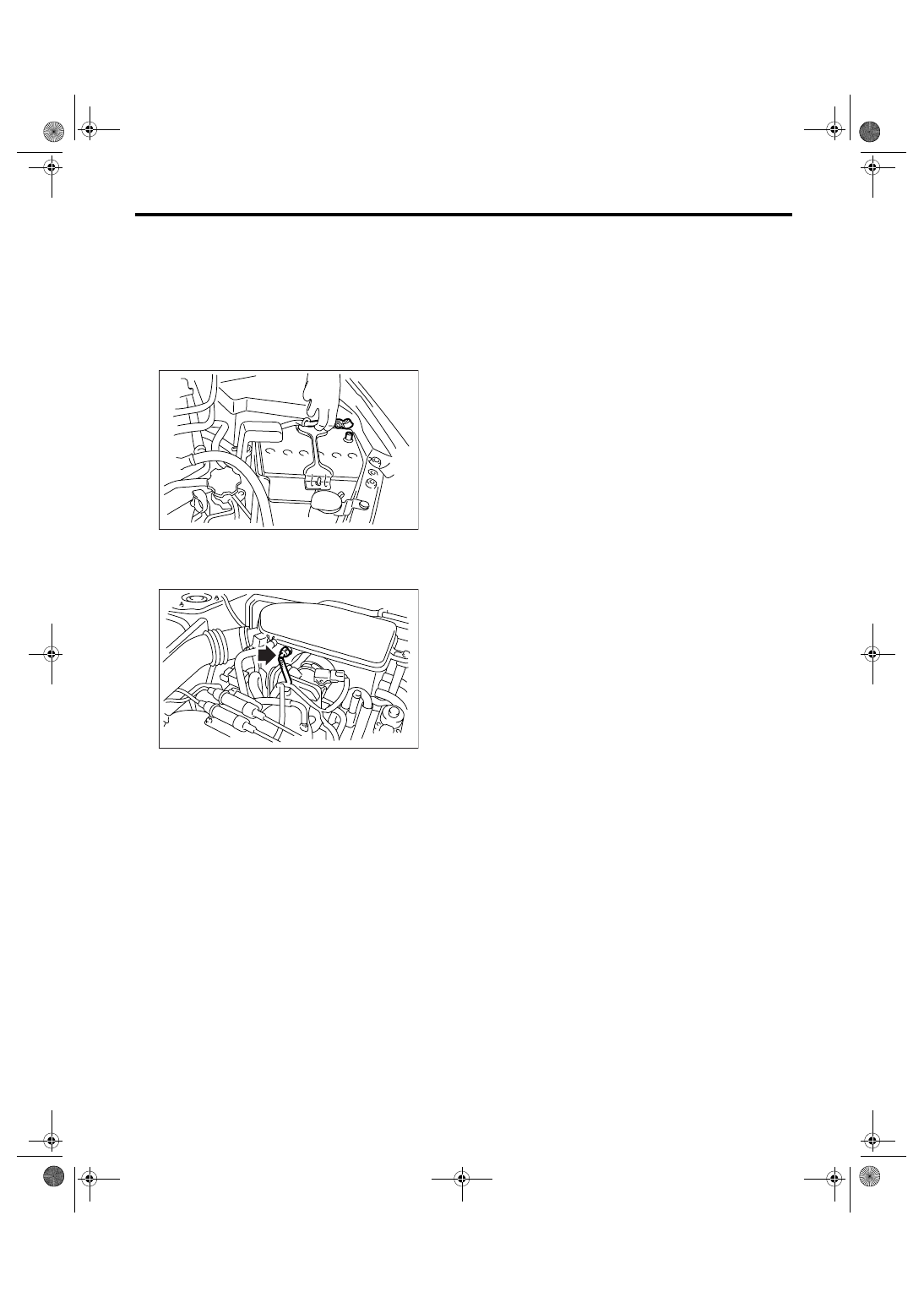
11.Intake Air Temperature Sen-
sor
A: REMOVAL
NOTE:
Intake air temperature sensor is installed to KA and
KS model.
1) Disconnect the ground cable from battery.
2) Disconnect the connector from intake air tem-
perature sensor.
3) Remove the intake air temperature sensor.
B: INSTALLATION
Install in the reverse order of removal.
IN-00203
FU-02080
FU(H4SO 2.5)-28
FUEL INJECTION (FUEL SYSTEMS)
Tumble Generator Valve Assembly
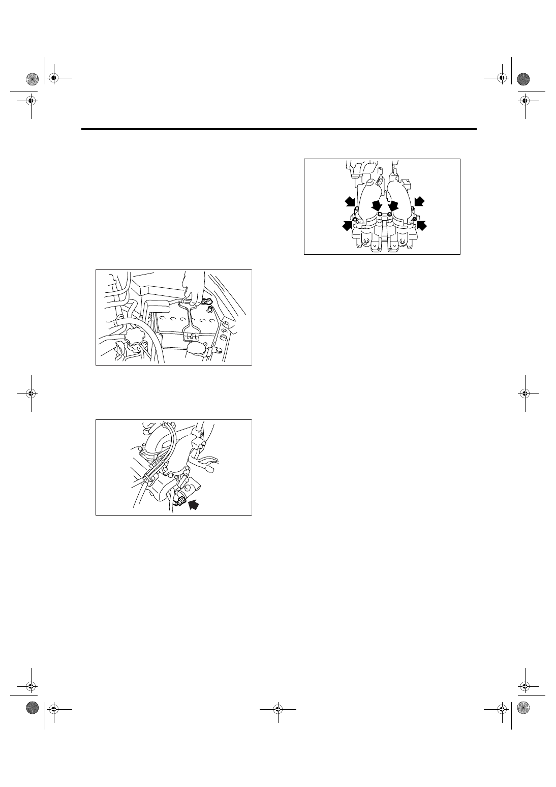
12.Tumble Generator Valve As-
sembly
A: REMOVAL
NOTE:
Tumble generator valve is installed to EC, EK, K4,
EH and ER model.
1) Release the fuel pressure. <Ref. to FU(H4SO
2.5)-41, RELEASING OF FUEL PRESSURE,
PROCEDURE, Fuel.>
2) Open the fuel filler flap lid, and remove the fuel
filler cap.
3) Disconnect the ground cable from battery.
4) Remove the intake manifold.
<Ref. to FU(H4SO 2.5)-12, REMOVAL, Intake
Manifold.>
5) Disconnect the connector from tumble generator
valve actuator.
6) Remove the fuel injectors.
<Ref. to FU(H4SO 2.5)-32, REMOVAL, Fuel Injec-
tor.>
7) Remove the tumble generator valve body from
intake manifold.
B: INSTALLATION
Install in the reverse order of removal.
NOTE:
Use a new gasket.
Tightening torque:
8.75 N
⋅
m (0.89 kgf-m, 6.5 ft-lb)
IN-00203
FU-01107
FU-01104
FU(H4SO 2.5)-29
FUEL INJECTION (FUEL SYSTEMS)
Tumble Generator Valve Actuator
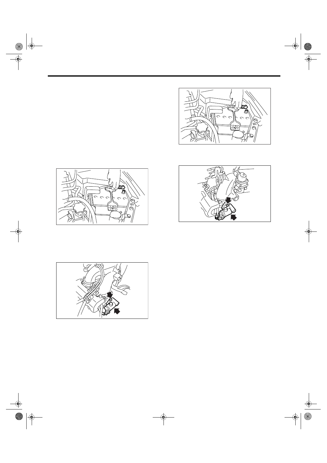
13.Tumble Generator Valve Ac-
tuator
A: REMOVAL
NOTE:
Tumble generator valve actuator is installed to EC,
EK, K4, EH and ER model.
1. RH SIDE
1) Release the fuel pressure. <Ref. to FU(H4SO
2.5)-41, RELEASING OF FUEL PRESSURE,
PROCEDURE, Fuel.>
2) Open the fuel filler flap lid, and remove the fuel
filler cap.
3) Disconnect the ground cable from battery.
4) Remove the intake manifold.
<Ref. to FU(H4SO 2.5)-12, REMOVAL, Intake
Manifold.>
5) Disconnect the connector from tumble generator
valve RH.
6) Remove the tumble generator valve RH.
2. LH SIDE
1) Release the fuel pressure. <Ref. to FU(H4SO
2.5)-41, RELEASING OF FUEL PRESSURE,
PROCEDURE, Fuel.>
2) Open the fuel filler flap lid, and remove the fuel
filler cap.
3) Disconnect the ground cable from battery.
4) Disconnect the connector from tumble generator
valve LH.
5) Remove the tumble generator valve LH.
B: INSTALLATION
1. RH SIDE
Install in the reverse order of removal.
Tightening torque:
6 N
⋅
m (0.61 kgf-m, 4.4 ft-lb)
2. LH SIDE
Install in the reverse order of removal.
Tightening torque:
6 N
⋅
m (0.61 kgf-m, 4.4 ft-lb)
IN-00203
FU-01108
IN-00203
FU-01109
FU(H4SO 2.5)-30
FUEL INJECTION (FUEL SYSTEMS)
Tumble Generator Valve Position Sensor
14.Tumble Generator Valve Po-
sition Sensor
A: SPECIFICATION
NOTE:
Tumble generator valve position sensor is installed
to EC, EK, K4, EH and ER model.
Do not remove the tumble generator valve position
sensor from tumble generator valve assembly,
since it cannot be adjusted during installation.
Refer to “Tumble Generator Valve ASSY” for re-
moval and installation procedures. <Ref. to
FU(H4SO 2.5)-28, REMOVAL, Tumble Generator
Valve Assembly.>
<Ref. to FU(H4SO 2.5)-28, INSTALLATION, Tum-
ble Generator Valve Assembly.>
Нет комментариевНе стесняйтесь поделиться с нами вашим ценным мнением.
Текст