Subaru Legacy (2005 year). Service manual — part 564
4AT(diag)-93
AUTOMATIC TRANSMISSION (DIAGNOSTICS)
Diagnostic Procedure with Diagnostic Trouble Code (DTC)
Step
Check
Yes
No
1
CHECK ENGINE GROUND TERMINALS.
Have engine ground terminals
been tightened securely?
Tighten the engine
ground terminals.
2
CHECK GROUND CIRCUIT FOR ECM.
1) Turn the ignition switch to OFF.
2) Disconnect the connector from ECM.
3) Measure the resistance of harness
between ECM and engine ground.
Connector & terminal
2.0 L model and 2.5 L KS, KA model
(B134) No. 2 — Engine ground:
(B134) No. 7 — Engine ground:
(B135) No. 5 — Engine ground:
(B135) No. 6 — Engine ground:
(B136) No. 1 — Engine ground:
(B136) No. 2 — Engine ground:
(B136) No. 5 — Engine ground:
(B136) No. 6 — Engine ground:
(B137) No. 1 — Engine ground:
2.5 L EC, EK, K4 model
(B134) No. 7 — Engine ground:
(B134) No. 6 — Engine ground:
(B135) No. 1 — Engine ground:
(B135) No. 4 — Engine ground:
(B135) No. 12 — Engine ground:
(B137) No. 1 — Engine ground:
(B137) No. 2 — Engine ground:
(B137) No. 3 — Engine ground:
(B137) No. 7 — Engine ground:
Is the resistance less than 5
Ω?
Repair the open
circuit of harness
between ECM
connector and
engine grounding
terminal.
3
CHECK ACCELERATOR PEDAL POSITION
SENSOR.
1) Disconnect the connectors from accelerator
pedal position sensor.
2) Measure the resistance between accelera-
tor pedal position sensor connector recepta-
cle’s terminals.
Connector & terminal
No. 1 — No. 6:
Is the resistance 0.75 — 3.15
k
Ω?
Replace the accel-
erator pedal posi-
tion sensor.
4
CHECK ACCELERATOR PEDAL POSITION
SENSOR.
Measure the resistance between accelerator
pedal position sensor connector receptacle’s
terminals.
Connector & terminal
No. 6 — No. 2:
Is the resistance 0.15 — 1.05
k
Ω?
Replace the accel-
erator pedal posi-
tion sensor.
5
CHECK HARNESS CONNECTOR BETWEEN
TCM AND ACCELERATOR PEDAL POSI-
TION SENSOR.
1) Disconnect the connector from TCM.
2) Measure the resistance of harness
between TCM and accelerator pedal position
sensor connector.
Connector & terminal
(B54) No. 19 — (B315) No. 2:
Is the resistance less than 1
Ω?
Repair the open
circuit of harness
between TCM and
accelerator pedal
position sensor
connector, and
poor contact in
coupling connec-
tor.
6
CHECK HARNESS CONNECTOR BETWEEN
TCM AND ACCELERATOR PEDAL POSI-
TION SENSOR.
Measure the resistance of harness between
TCM connector and chassis ground.
Connector & terminal
(B54) No. 19 — Chassis ground:
Is the resistance more than 1
M
Ω?
Repair the short
circuit of harness
between TCM and
accelerator pedal
position sensor
connector.
4AT(diag)-94
AUTOMATIC TRANSMISSION (DIAGNOSTICS)
Diagnostic Procedure with Diagnostic Trouble Code (DTC)
7
CHECK HARNESS CONNECTOR BETWEEN
ECM AND ACCELERATOR PEDAL POSI-
TION SENSOR.
1) Remove the connector from ECM.
2) Measure the resistance of harness
between accelerator pedal position sensor
connector and chassis ground.
Connector & terminal
(B315) No. 6 — Chassis ground:
Is the resistance more than 1
M
Ω?
Repair the short
circuit of harness
between ECM and
accelerator pedal
position sensor.
8
CHECK INPUT SIGNAL FOR TCM USING
SUBARU SELECT MONITOR.
1) Connect the connectors to TCM, accelera-
tor pedal position sensor and ECM.
2) Connect the Subaru Select Monitor to data
link connector.
3) Turn the ignition switch to ON (engine
OFF).
4) Turn the Subaru Select Monitor power
switch to ON.
5) Fully close the throttle.
6) Read the data of accelerator pedal position
sensor using Subaru Select Monitor.
• Accelerator pedal position sensor input sig-
nal is indicated.
Is the voltage more than 0.2 V? Even if the SPORT
indicator light is
blinking, the cir-
cuit has returned
to normal condi-
tion at this time. A
temporary poor
contact of connec-
tor or harness may
be the cause.
Repair the har-
ness or connector
in accelerator
pedal position sen-
sor circuit.
9
CHECK POOR CONTACT.
Is there poor contact in accel-
erator pedal position sensor
circuit?
Repair the poor
contact.
Replace the TCM.
<Ref. to 4AT-66,
Transmission Con-
trol Module
(TCM).>
Step
Check
Yes
No
4AT(diag)-95
AUTOMATIC TRANSMISSION (DIAGNOSTICS)
Diagnostic Procedure with Diagnostic Trouble Code (DTC)
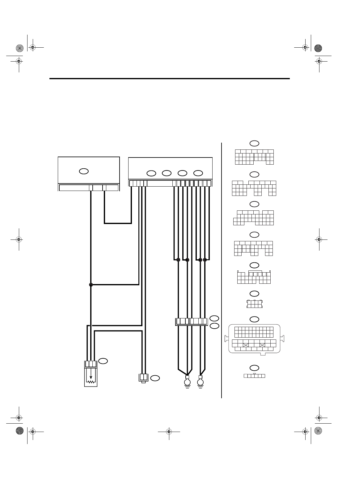
Y: DTC P1709 THROTTLE POSITION SENSOR CIRCUIT HIGH INPUT
DTC DETECTING CONDITION:
The input signal circuit of accelerator pedal position sensor is shorted.
TROUBLE SYMPTOM:
• Shift point is too high or too low.
• Excessive shift shock
• Tight corner braking phenomenon is occurred.
WIRING DIAGRAM:
• 2.0 L LHD and 2.5 L KS model
AT-01894
2 3 4
1
5 6
B54
B21
1 2
7
8 9
5
6
3
4
10 11 12
19 20 21
13 14 15 16
17 18
22 23 24
B315
B83
B21
B134
B83
B54
TCM
A:
B135
B:
B136
C:
ECM
B137
D:
E2
52
37
35
34
1
2
6
19
D30
C17
C18
B5
B6
C6
C1
A2
C2
A7
D1
E
E
1
2
JOINT CONNECTOR
ACCELERATOR PEDAL POSITION SENSOR
B315
C5
36
B137
5
6
7
8
2
1
9
4
3
10
22 23
11 12 13 14 15
24 25
26
16 17
18 19 20 21
27
28 29
30 31
B134
5
6
7
8
2
1
9
4
3
10
24
22 23
25
11 12 13 14 15
26 27
28
16 17
18 19 20 21
33 34
29
32
30 31
B136
5
6
7 8
2
1
9
4
3
10
24
22 23
25
11 12 13 14 15
26 27
28
16
17 18 19 20 21
33 34
29
32
30
31
35
B135
5
6
7
8
2
1
9
4
3
10
24
22 23
25
11 12 13 14 15
26 27
28
16 17 18 19
20 21
29 30 31
32 33
34 35
1 2 3 4
5 6 7 8
1 2 3 4
12 13 14 15
5 6 7 8
16 17 18 19
9 10 11
20 21 22
23 24 25 26 27 28 29 30 31 32 33
35
34
37
36
39
38
41
40
43
42
44
45
47
46
49
48
51
50
53
52
54
A:
B:
C:
D:
D18
10
4AT(diag)-96
AUTOMATIC TRANSMISSION (DIAGNOSTICS)
Diagnostic Procedure with Diagnostic Trouble Code (DTC)
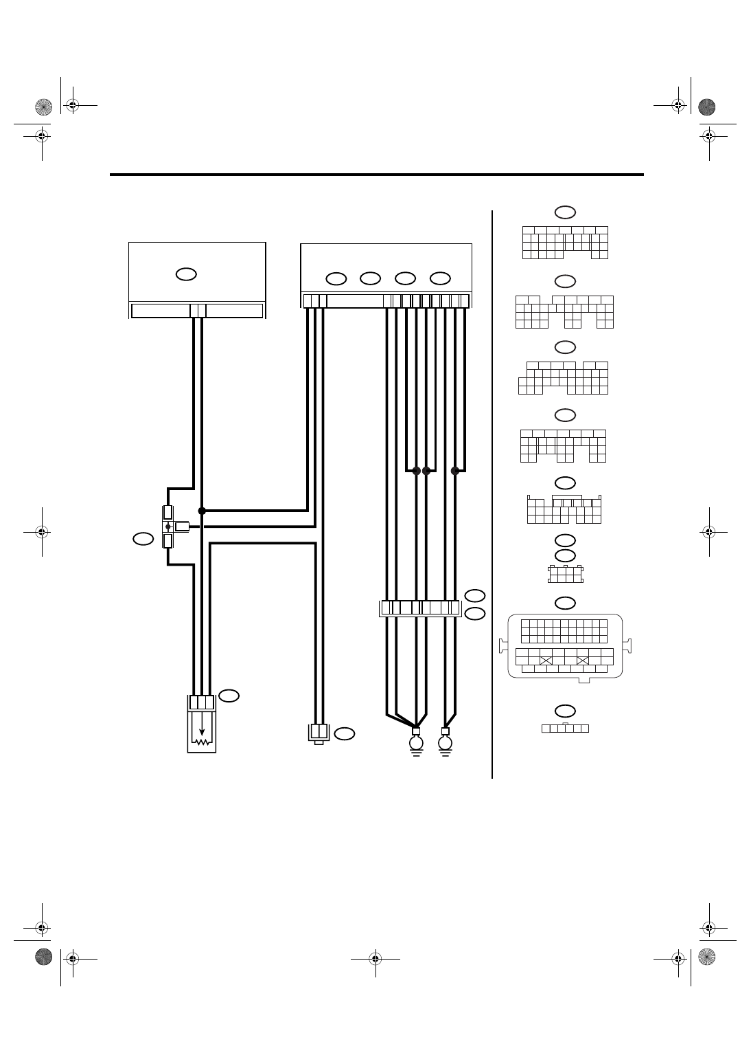
• 2.5 L EC, K4 model
AT-01494
2 3 4
1
5 6
B54
B21
1 2
7
8 9
5
6
3
4
10 11 12
19 20 21
13 14 15 16
17 18
22 23 24
B315
B83
B21
B134
B83
B54
TCM
A:
B135
B:
B136
C:
ECM
B137
D:
E2
37
52
47
35
36
1
2
6
10
19
C28
C16
C35
A6
A7
D7
B12
B4
D1
D2
B1
E
E
1
2
JOINT CONNECTOR
ACCELERATOR PEDAL POSITION SENSOR
B315
5
1
6
D3
34
B137
5
6
7
8
2
1
9
4
3
10
22 23
11 12 13 14 15
24 25
26
16 17
18 19 20 21
27
28 29
30 31
B134
5
6
7
8
2
1
9
4
3
10
24
22 23
25
11 12 13 14 15
26 27
28
16 17
18 19 20 21
33 34
29
32
30 31
B136
5
6
7 8
2
1
9
4
3
10
24
22 23
25
11 12 13 14 15
26 27
28
16
17 18 19 20 21
33 34
29
32
30
31
35
B135
5
6
7
8
2
1
9
4
3
10
24
22 23
25
11 12 13 14 15
26 27
28
16 17 18 19
20 21
29 30 31
32 33
34 35
1 2 3 4
5 6 7 8
1 2 3 4
12 13 14 15
5 6 7 8
16 17 18 19
9 10 11
20 21 22
23 24 25 26 27 28 29 30 31 32 33
35
34
37
36
39
38
41
40
43
42
44
45
47
46
49
48
51
50
53
52
54
A:
B:
C:
D:
B122
B122
JOINT
CONNECTOR
Нет комментариевНе стесняйтесь поделиться с нами вашим ценным мнением.
Текст