Subaru Legacy (2005 year). Service manual — part 140
EN(H4SO 2.0)(diag)-149
ENGINE (DIAGNOSTICS)
Diagnostic Procedure with Diagnostic Trouble Code (DTC)
6
CHECK HARNESS BETWEEN EGR SOLE-
NOID VALVE AND ECM CONNECTOR.
1) Turn the ignition switch to OFF.
2) Disconnect the connector from EGR sole-
noid valve and ECM.
3) Measure the resistance of harness
between EGR solenoid valve and ECM con-
nector.
Connector & terminal
(B134) No. 4 — (E18) No. 6:
(B134) No. 12 — (E18) No. 1:
(B134) No. 3 — (E18) No. 4:
(B134) No. 13 — (E18) No. 3:
Is the resistance less than 1
Ω?
Repair the open
circuit of harness
between ECM and
EGR solenoid
valve connector.
7
CHECK HARNESS BETWEEN EGR SOLE-
NOID VALVE AND ECM CONNECTOR.
Measure the resistance of harness between
EGR solenoid valve and chassis ground.
Connector & terminal
(B134) No. 4 — Chassis ground:
(B134) No. 3 — Chassis ground:
(B134) No. 12 — Chassis ground:
(B134) No. 13 — Chassis ground:
Is the resistance more than 1
M
Ω?
Repair the short
circuit of harness
between main
relay and EGR
solenoid valve
connector.
8
CHECK POOR CONTACT.
Check poor contact in ECM and EGR solenoid
valve connector.
Is there poor contact of ECM or
EGR solenoid valve connec-
tor?
Repair the poor
contact of ECM
and EGR solenoid
valve connector.
Even if the mal-
function indicator
light illuminates,
the circuit has
returned to the
specified condi-
tion at this time.
Step
Check
Yes
No
EN(H4SO 2.0)(diag)-150
ENGINE (DIAGNOSTICS)
Diagnostic Procedure with Diagnostic Trouble Code (DTC)
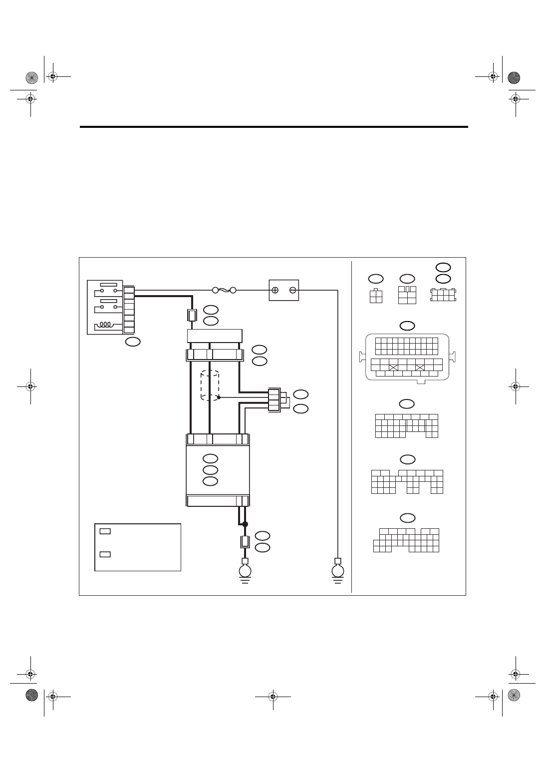
AJ:DTC P0420 CATALYST SYSTEM EFFICIENCY BELOW THRESHOLD
(BANK1)
DTC DETECTING CONDITION:
Detects when malfunction occurs in 2 continuous driving cycles.
TROUBLE SYMPTOM:
• Engine stalls.
• Idle mixture is out of specifications.
CAUTION:
After repair or replacement of faulty parts, perform Clear Memory Mode <Ref. to EN(H4SO 2.0)(diag)-
38, OPERATION, Clear Memory Mode.> and Inspection Mode <Ref. to EN(H4SO 2.0)(diag)-32, PRO-
CEDURE, Inspection Mode.>.
WIRING DIAGRAM:
EN-03476
B47
T5
3
4
5
6
1
2
1 2
3 4
BATTERY
B47
MAIN RELAY
1
2
4
6
3
5
A1
C19
C18
C30
B5
B6
REAR
OXYGEN SENSOR
ECM
1
4
3
2
52
B21
T5
E2
1
B135
B:
SBF-5
C: B136
E
E
A: B134
B134
5
6
7
8
2
1
9
4
3
10
24
22 23
25
11 12 13 14 15
26 27
28
16 17
18 19 20 21
33 34
29
32
30 31
B136
5
6
7 8
2
1
9
4
3
10
24
22 23
25
11 12 13 14 15
26 27
28
16
17 18 19 20 21
33 34
29
32
30
31
35
B135
5
6
7
8
2
1
9
4
3
10
24
22 23
25
11 12 13 14 15
26 27
28
16 17 18 19
20 21
29 30 31
32 33
34 35
A:
B:
C:
B21
1 2 3 4
12 13 14 15
5 6 7 8
16 17 18 19
9 10 11
20 21 22
23 24 25 26 27 28 29 30 31 32 33
35
34
37
36
39
38
41
40
43
42
44
45
47
46
49
48
51
50
53
52
54
1 2 3 4
5 6 7 8
B138
B83
1
T5
B19
2
2
B19
B83
B138
:LHD
:RHD
*
*
*
*
1
*
: TERMINAL No. RANDOM
ARRANGEMENT AMONG
1,2,5, AND 6
2
*
: TERMINAL No. RANDOM
ARRANGEMENT AMONG
3,4,7, AND 8
EN(H4SO 2.0)(diag)-151
ENGINE (DIAGNOSTICS)
Diagnostic Procedure with Diagnostic Trouble Code (DTC)
Step
Check
Yes
No
1
CHECK FOR ANY OTHER DTC ON DIS-
PLAY.
Is any other DTC displayed?
Inspect the rele-
vant DTC using
“List of Diagnostic
Trouble Code
(DTC)”. <Ref. to
EN(H4SO
2.0)(diag)-64, List
of Diagnostic Trou-
ble Code (DTC).>
NOTE:
In this case, it is
not necessary to
inspect DTC
P0420.
2
CHECK HARNESS BETWEEN ECM AND
REAR OXYGEN SENSOR CONNECTOR.
1) Turn the ignition switch to OFF.
2) Disconnect the connectors from ECM and
rear oxygen sensor.
3) Measure the resistance of harness
between ECM and rear oxygen sensor con-
nector.
Connector & terminal
(B136) No. 19 — (B19) No. 4:
(B136) No. 18 — (B19) No. 3:
Is the resistance less than 1
Ω?
Repair open circuit
in harness
between ECM and
rear oxygen sen-
sor connector.
3
CHECK HARNESS BETWEEN REAR OXY-
GEN SENSOR AND ECM CONNECTOR.
Measure the resistance between rear oxygen
sensor harness connector and chassis ground.
Connector & terminal
(B136) No. 30 — Chassis ground:
Is the resistance less than 1
Ω?
Repair open circuit
in harness
between ECM and
rear oxygen sen-
sor connector.
4
CHECK EXHAUST SYSTEM.
Check for gas leaks or air suction caused by
loose or dislocated nuts and bolts, and open
hole at exhaust pipes.
NOTE:
Check the following positions.
• Between cylinder head and front exhaust
pipe
• Between front exhaust pipe and front cata-
lytic converter
• Between front catalytic converter and rear
catalytic converter
Is there a fault in exhaust sys-
tem?
Repair or replace
the exhaust sys-
tem. <Ref. to
EX(H4SO 2.0)-2,
General Descrip-
tion.>
5
CHECK CATALYTIC CONVERTER.
Is there damage at rear face or
front face of front catalyst?
Replace the cata-
lytic converter.
<Ref. to EC(H4SO
2.0)-3, Front Cata-
lytic Converter.>
Contact the SUB-
ARU Dealer.
EN(H4SO 2.0)(diag)-152
ENGINE (DIAGNOSTICS)
Diagnostic Procedure with Diagnostic Trouble Code (DTC)
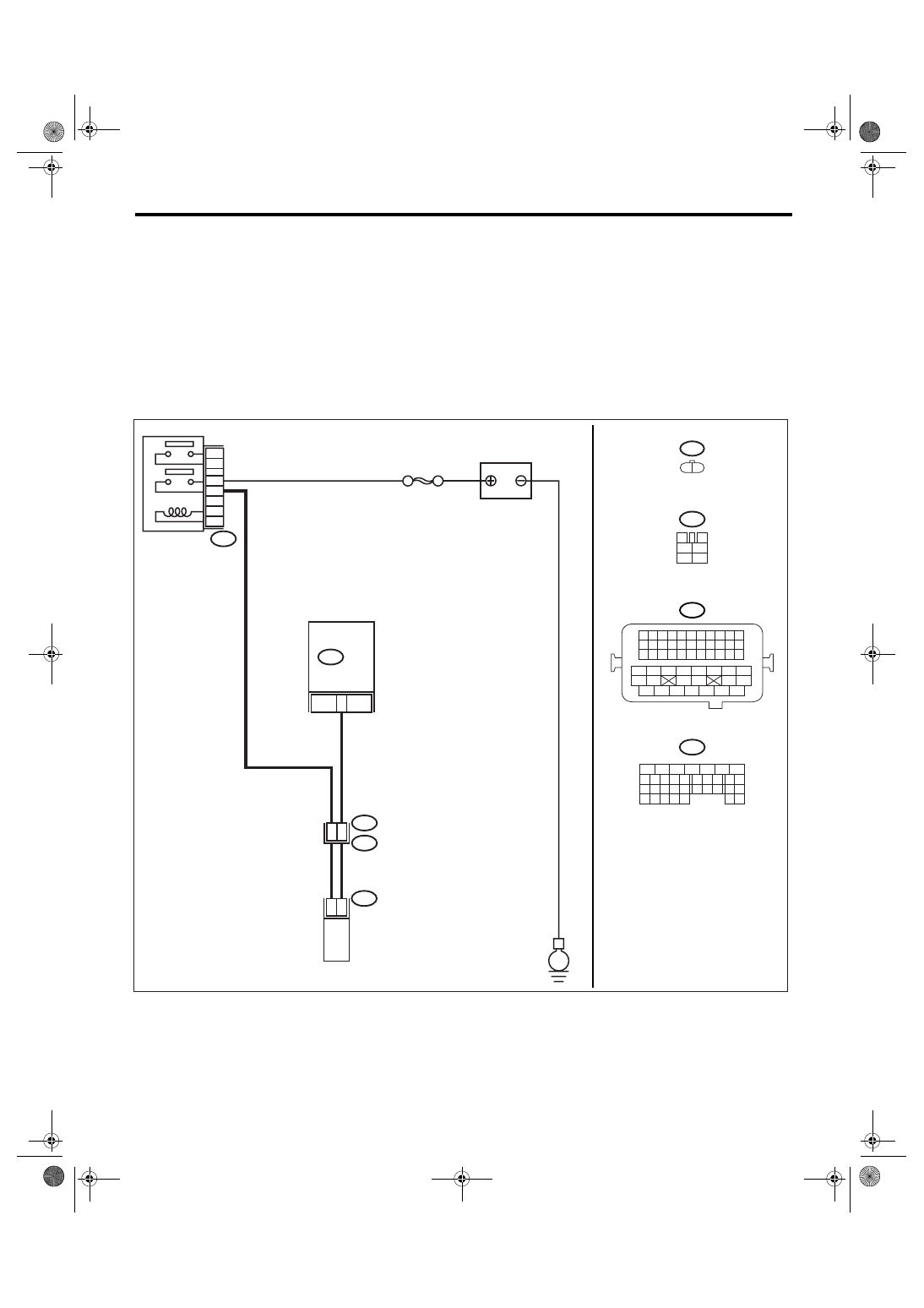
AK:DTC P0458 EVAPORATIVE EMISSION SYSTEM PURGE CONTROL VALVE
CIRCUIT LOW
DTC DETECTING CONDITION:
Detects when malfunction occurs in 2 continuous driving cycles.
TROUBLE SYMPTOM:
Erroneous idling
CAUTION:
After repair or replacement of faulty parts, perform Clear Memory Mode <Ref. to EN(H4SO 2.0)(diag)-
38, OPERATION, Clear Memory Mode.> and Inspection Mode <Ref. to EN(H4SO 2.0)(diag)-32, PRO-
CEDURE, Inspection Mode.>.
WIRING DIAGRAM:
EN-03484
PURGE CONTROL
SOLENOID VALVE
E4
B21
E2
B47
B47
3
4
1
2
5
6
SBF-7
BATTERY
MAIN RELAY
1
2
4
6
3
5
8
2
1
48
41
B134
ECM
E
B21
1 2 3 4
12 13 14 15
5 6 7 8
16 17 18 19
9 10 11
20 21 22
23 24 25 26 27 28 29 30 31 32 33
35
34
37
36
39
38
41
40
43
42
44
45
47
46
49
48
51
50
53
52
54
B134
5
6
7
8
2
1
9
4
3
10
24
22 23
25
11 12 13 14 15
26 27
28
16 17
18 19 20 21
33 34
29
32
30 31
E4
1 2
Нет комментариевНе стесняйтесь поделиться с нами вашим ценным мнением.
Текст