Subaru Legacy (2005 year). Service manual — part 575
4AT(diag)-137
AUTOMATIC TRANSMISSION (DIAGNOSTICS)
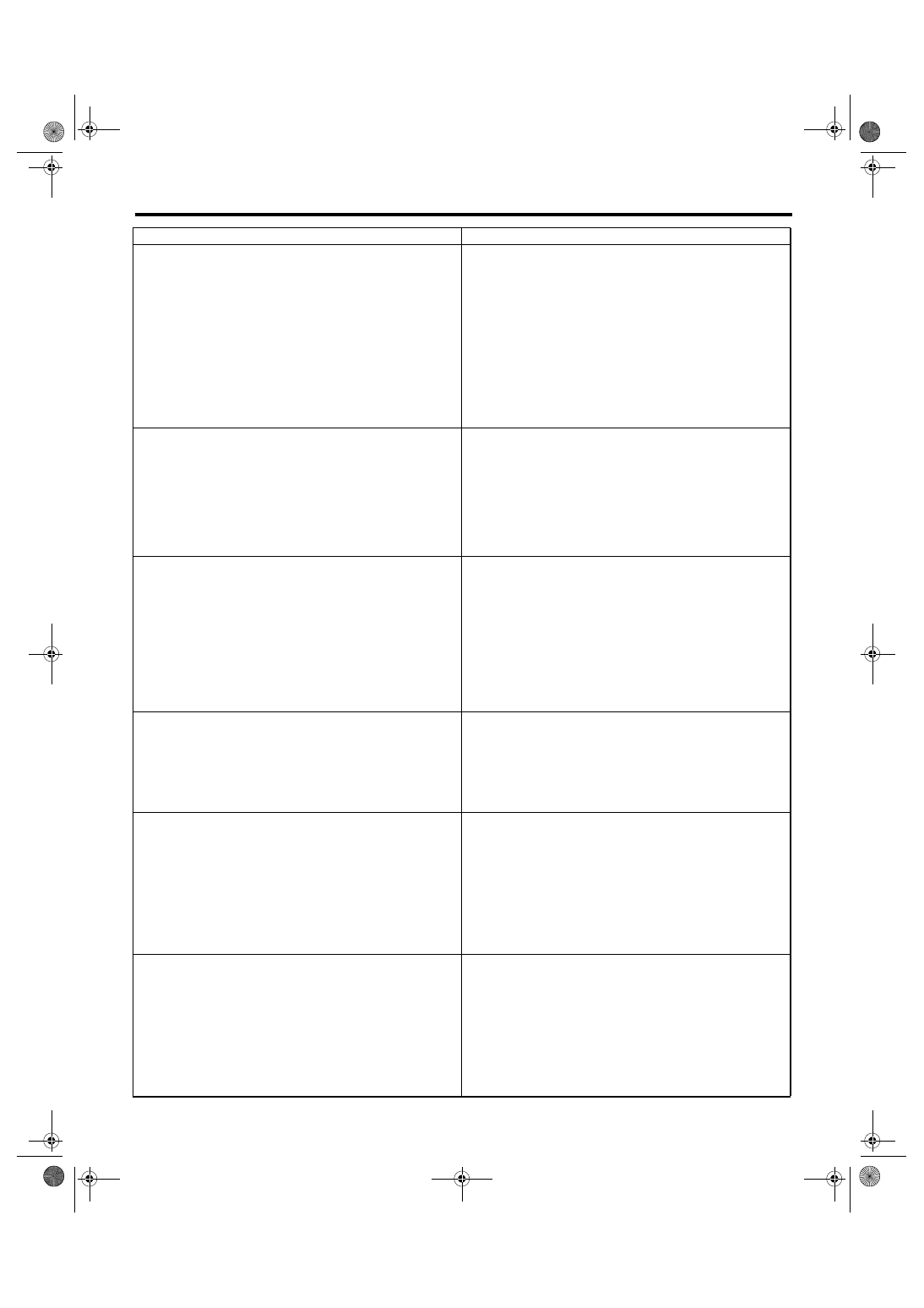
Diagnostics with Phenomenon
Shock occurs from 2nd to 3rd gear.
• TCM
• Torque converter turbine speed sensor
• Accelerator pedal position sensor
• 2-4 brake duty solenoid
• ATF temperature sensor
• Line pressure linear solenoid
• Low & reverse duty solenoid
• Control valve
• High clutch
• 2-4 brake
• ATF deterioration
• Engine performance
• High clutch duty solenoid
Slippage occurs from 2nd to 3rd gear.
• TCM
• Accelerator pedal position sensor
• 2-4 brake duty solenoid
• ATF temperature sensor
• Line pressure linear solenoid
• Control valve
• High clutch
• 2-4 brake
• Low & reverse duty solenoid
Shock occurs from 3rd to 4th gear.
• TCM
• Torque converter turbine speed sensor
• Accelerator pedal position sensor
• 2-4 brake duty solenoid
• ATF temperature sensor
• Line pressure linear solenoid
• Control valve
• Low clutch duty solenoid
• 2-4 brake
• ATF deterioration
• Engine performance
Slippage occurs from 3rd to 4th gear.
• TCM
• Accelerator pedal position sensor
• 2-4 brake duty solenoid
• ATF temperature sensor
• Line pressure linear solenoid
• Control valve
• 2-4 brake
Shock occurs when select lever is shifted from 3rd gear to 2nd
gear.
• TCM
• Torque converter turbine speed sensor
• Accelerator pedal position sensor
• ATF temperature sensor
• Line pressure linear solenoid
• Control valve
• 2-4 brake duty solenoid
• 2-4 brake
• ATF deterioration
• High clutch duty solenoid
Shock occurs when select lever is shifted from 2nd gear to 1st
gear.
• TCM
• Torque converter turbine speed sensor
• Accelerator pedal position sensor
• ATF temperature sensor
• Line pressure linear solenoid
• Control valve
• Low & reverse clutch
• ATF deterioration
• 2-4 brake duty solenoid
• Low & reverse brake duty solenoid
Symptom
Faulty parts
4AT(diag)-138
AUTOMATIC TRANSMISSION (DIAGNOSTICS)
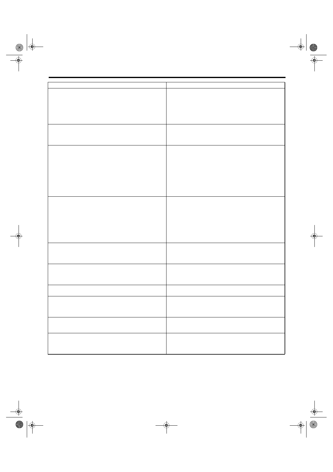
Diagnostics with Phenomenon
Shock occurs when accelerator pedal is released at medium
speeds.
• TCM
• Accelerator pedal position sensor
• ATF temperature sensor
• Line pressure linear solenoid
• Control valve
• Lock-up damper
• Engine performance
Vibration occurs during straight-forward operation.
• TCM
• Lock-up duty solenoid
• Lock-up facing
• Lock-up damper
Vibration occurs during turns. (tight corner braking phenome-
non)
• TCM
• Front vehicle speed sensor
• Rear vehicle speed sensor
• Accelerator pedal position sensor
• ATF temperature sensor
• Transfer clutch
• Transfer valve
• Transfer duty solenoid
• ATF deterioration
• Harness
Front wheel slippage occurs during standing starts.
• TCM
• Front vehicle speed sensor
• Accelerator pedal position sensor
• ATF temperature sensor
• Control valve
• Transfer clutch
• Transfer valve
• Transfer pipe
• Transfer duty solenoid
It is not set in FWD mode.
• TCM
• Transfer clutch
• Transfer valve
• Transfer duty solenoid
Select lever is hard to move.
• Select cable
• Select lever
• Detent spring
• Manual plate
Select lever is excessively hard to move. (unreasonable resis-
tance)
• Detent spring
• Manual plate
Select lever slips out of operation during acceleration or while
driving on rough terrain.
• Select cable
• Select lever
• Detent spring
• Manual plate
Can not set to manual mode.
• SPORT mode switch
• TCM
• Body integrated module
Gear does not change though the select lever is operated in
manual mode.
• Up shift switch
• Down shift switch
• TCM
• Body integrated module
Symptom
Faulty parts
AUTOMATIC TRANSMISSION
5AT
Page
General Description . . . . . . . . . . . . . . . . . . . . . 2
Automatic Transmission Fluid . . . . . . . . . . . . . . . . ...28
Differential Gear Oil. . . . . . . . . . . . . . . . . . . . ...30
Road Test. . . . . . . . . . . . . . . . . . . . . . . . ..31
Stall Test . . . . . . . . . . . . . . . . . . . . . . . . ...32
Time Lag Test . . . . . . . . . . . . . . . . . . . . . . ...34
Line Pressure Test . . . . . . . . . . . . . . . . . . . . . 35
Transfer Clutch Pressure Test . . . . . . . . . . . . . . . . ..36
Automatic Transmission Assembly . . . . . . . . . . . . . . ...38
Transmission Mounting System . . . . . . . . . . . . . . . . 47
Extension Case Oil Seal . . . . . . . . . . . . . . . . . . ...49
Differential Side Retainer Oil Seal. . . . . . . . . . . . . . . .50
Inhibitor Switch. . . . . . . . . . . . . . . . . . . . . . ..51
Front Vehicle Speed Sensor . . . . . . . . . . . . . . . . . .52
Rear Vehicle Speed Sensor. . . . . . . . . . . . . . . . . ..54
Turbine Speed Sensor 1 . . . . . . . . . . . . . . . . . . ...57
Control Valve Body . . . . . . . . . . . . . . . . . . . . ...58
ATF Filter . . . . . . . . . . . . . . . . . . . . . . . . ..60
Transmission Control Module (TCM) . . . . . . . . . . . . . . 61
Lateral G Sensor . . . . . . . . . . . . . . . . . . . . . ...62
ATF Cooler Pipe and Hose . . . . . . . . . . . . . . . . . ...63
Air Breather Hose. . . . . . . . . . . . . . . . . . . . . ..68
Oil Charge Pipe. . . . . . . . . . . . . . . . . . . . . . .69
Torque Converter Assembly . . . . . . . . . . . . . . . . . .70
Extension Case and Intermediate Case. . . . . . . . . . . . . 71
Transfer Clutch. . . . . . . . . . . . . . . . . . . . . . ..73
Rear Drive Shaft. . . . . . . . . . . . . . . . . . . . . . 75
Reduction Driven Gear. . . . . . . . . . . . . . . . . . . ..76
Center Differential Carrier . . . . . . . . . . . . . . . . . . .78
Parking Pawl . . . . . . . . . . . . . . . . . . . . . . . .80
Converter Case . . . . . . . . . . . . . . . . . . . . . . .82
Oil Pump Cover. . . . . . . . . . . . . . . . . . . . . . .84
Drive Pinion Shaft Assembly. . . . . . . . . . . . . . . . . .87
Front Differential Assembly . . . . . . . . . . . . . . . . . ...92
AT Main Case . . . . . . . . . . . . . . . . . . . . . . ...97
Transmission Control Device . . . . . . . . . . . . . . . . ..107
5AT-2
AUTOMATIC TRANSMISSION
General Description
1. General Description
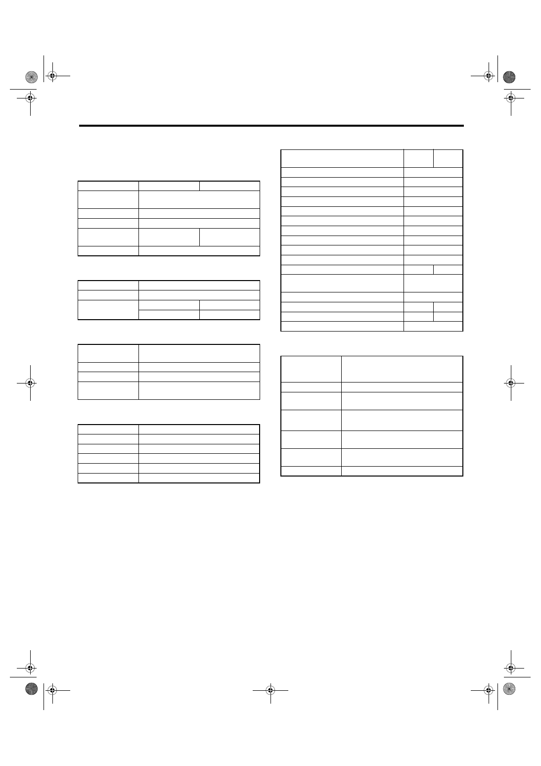
A: SPECIFICATION
1. TORQUE CONVERTER CLUTCH
2. OIL PUMP
3. TRANSMISSION CONTROL ELEMENT
4. TRANSMISSION GEAR RATIO
5. PLANETARY GEAR AND PLATE
6. SELECTOR POSITION
Model
Turbo
Non-turbo
Type
Symmetric, 3 element, single stage,
2 phase torque converter
Stall torque ratio
2.1
Nominal diameter
250 mm (9.84 in)
Stall speed (at sea
level)
3,100 — 3,500
rpm
2,400 — 2,800
rpm
One-way clutch
Sprague type one-way clutch
Type
Internal gear discharge pump
Driving method
Driven by engine
Number of teeth
Inner rotor
9
Outer rotor
10
Type
5-forward, 1-reverse,
double-row planetary gears
Multi-plate clutch
3 sets
Multi-plate brake
4 sets
One-way clutch
(sprague type)
3 sets
1st
3.540
2nd
2.264
3rd
1.471
4th
1.000
5th
0.834
Rev
2.370
Model
Turbo
Non-
turbo
Tooth number of front internal gear
106
Tooth number of front carrier
28
Tooth number of front sun gear
50
Tooth number of mid internal gear
78
Tooth number of mid carrier
18
Tooth number of mid sun gear
42
Tooth number of rear internal gear
110
Tooth number of rear carrier
24
Tooth number of rear sun gear
62
Drive plate number of front brake
2
Drive plate number of input clutch
6
5
Drive plate number of high & low
reverse clutch
4
Drive plate number of direct clutch
5
Drive plate number of reverse brake
5
6
Drive plate number of forward brake
5
4
Drive plate number of low coast brake
3
P (Park)
Transmission in neutral, output mem-
ber immovable, and engine start possi-
ble
R (Reverse)
Transmission in reverse for backing
N (Neutral)
Transmission in neutral and engine
start possible
D (Drive)
Automatic gear change
1st
←
→
2nd
←
→
3rd
←
→
4th
←
→
5th
Manual mode (+)
Manual gear change
1st
→ 2nd→ 3rd→ 4th→ 5th
Manual mode (
−)
Manual gear change
1st
← 2nd← 3rd← 4th← 5th
Control method
Wire cable type
Нет комментариевНе стесняйтесь поделиться с нами вашим ценным мнением.
Текст