Subaru Legacy (2005 year). Service manual — part 694
6MT-123
MANUAL TRANSMISSION AND DIFFERENTIAL
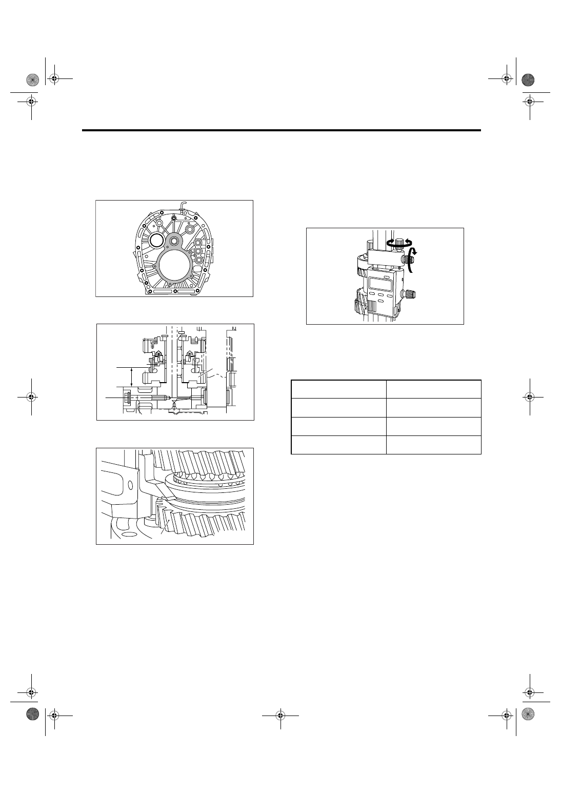
Shifter Fork and Rod
NOTE:
• Remove the remaining gasket on edge surface
with scraper, since the adapter plate is base point
of measurement.
• Do not place the height gauge on shaded area in
the figure during the measurement.
4) Press the reverse sleeve to reverse side idler
gear No. 2, then measure “T”.
NOTE:
• Set the indicator of height gauge near measuring
object, then lock the dial (1) as shown in the figure.
Turn dial (2) to set the indicator to edge surface of
reverse sleeve side.
• Measure five points of the sleeve turning every
approx. 72
°. Round off each two upper and lower
measurement value. Use the remaining middle val-
ue as measurement value.
5) According to measurement, calculate the re-
verse sleeve neutral position. Select the fork rod,
which applies to the calculated value from following
calculation formula.
Calculation formula: T + 4.8 mm (0.189 in)
T = Thickness
(A) Reverse idler gear No. 2.
(A) Reverse idler gear No. 2.
MT-00583
(A)
T
MT-00715
(A)
MT-00716
T + 4.8 mm (0.189 in)
mm (in)
Lot No. (Mark)
33.50 — 33.80
(1.3189 — 1.3307)
32816AA110 (1)
33.80 — 34.10
(1.3307 — 1.3425)
32816AA130 (None)
34.10 — 34.40
(1.3425 — 1.3543)
32816AA140 (2)
(2)
(1)
MT-00585
6MT-124
MANUAL TRANSMISSION AND DIFFERENTIAL
Clutch Housing
25.Clutch Housing
A: REMOVAL
1) Remove the manual transmission assembly
from vehicle. <Ref. to 6MT-34, REMOVAL, Manual
Transmission Assembly.>
2) Prepare the transmission for overhaul. <Ref. to
6MT-40, Preparation for Overhaul.>
3) Remove the oil pipe, neutral position switch,
back-up light switch and harness. <Ref. to 6MT-42,
REMOVAL, Oil Pipe.> <Ref. to 6MT-45, REMOV-
AL, Neutral Position Switch.> <Ref. to 6MT-43, RE-
MOVAL, Back-up Light Switch.>
4) Remove the extension case. <Ref. to 6MT-47,
REMOVAL, Extension Case.>
5) Remove the transfer driven gear. <Ref. to 6MT-
58, REMOVAL, Transfer Driven Gear.>
6) Remove the center differential. <Ref. to 6MT-60,
REMOVAL, Center Differential.>
7) Remove the oil pump. <Ref. to 6MT-61, RE-
MOVAL, Oil Pump.>
8) Remove the transmission case. <Ref. to 6MT-
64, REMOVAL, Transmission Case.>
9) Remove each gear assembly. <Ref. to 6MT-69,
REMOVAL, Main Shaft Assembly.>
10) Remove the drive pinion shaft assembly. <Ref.
to 6MT-96, REMOVAL, Drive Pinion Shaft Assem-
bly.>
11) Remove the front differential assembly. <Ref.
to 6MT-102, REMOVAL, Front Differential Assem-
bly.>
B: INSTALLATION
1) Install the pitching stopper bracket.
Tightening torque:
41 N
⋅
m (4.2 kgf-m, 30.2 ft-lb)
2) Install the front differential assembly. <Ref. to
6MT-103, INSTALLATION, Front Differential As-
sembly.>
3) Install the drive pinion shaft assembly. <Ref. to
6MT-96, INSTALLATION, Drive Pinion Shaft As-
sembly.>
4) Install each gear assembly at a time. <Ref. to
6MT-70, INSTALLATION, Main Shaft Assembly.>
5) Install the transmission case. <Ref. to 6MT-65,
INSTALLATION, Transmission Case.>
6) Install the oil pump. <Ref. to 6MT-62, INSTAL-
LATION, Oil Pump.>
7) Install the center differential. <Ref. to 6MT-60,
INSTALLATION, Center Differential.>
8) Install the transfer driven gear. <Ref. to 6MT-58,
INSTALLATION, Transfer Driven Gear.>
9) Install the extension case. <Ref. to 6MT-47, IN-
STALLATION, Extension Case.>
10) Install the oil pipe, neutral position switch,
back-up light switch and harness. <Ref. to 6MT-42,
INSTALLATION, Oil Pipe.> <Ref. to 6MT-45, IN-
STALLATION, Neutral Position Switch.> <Ref. to
6MT-43, INSTALLATION, Back-up Light Switch.>
11) Install the manual transmission assembly into
vehicle. <Ref. to 6MT-36, INSTALLATION, Manual
Transmission Assembly.>
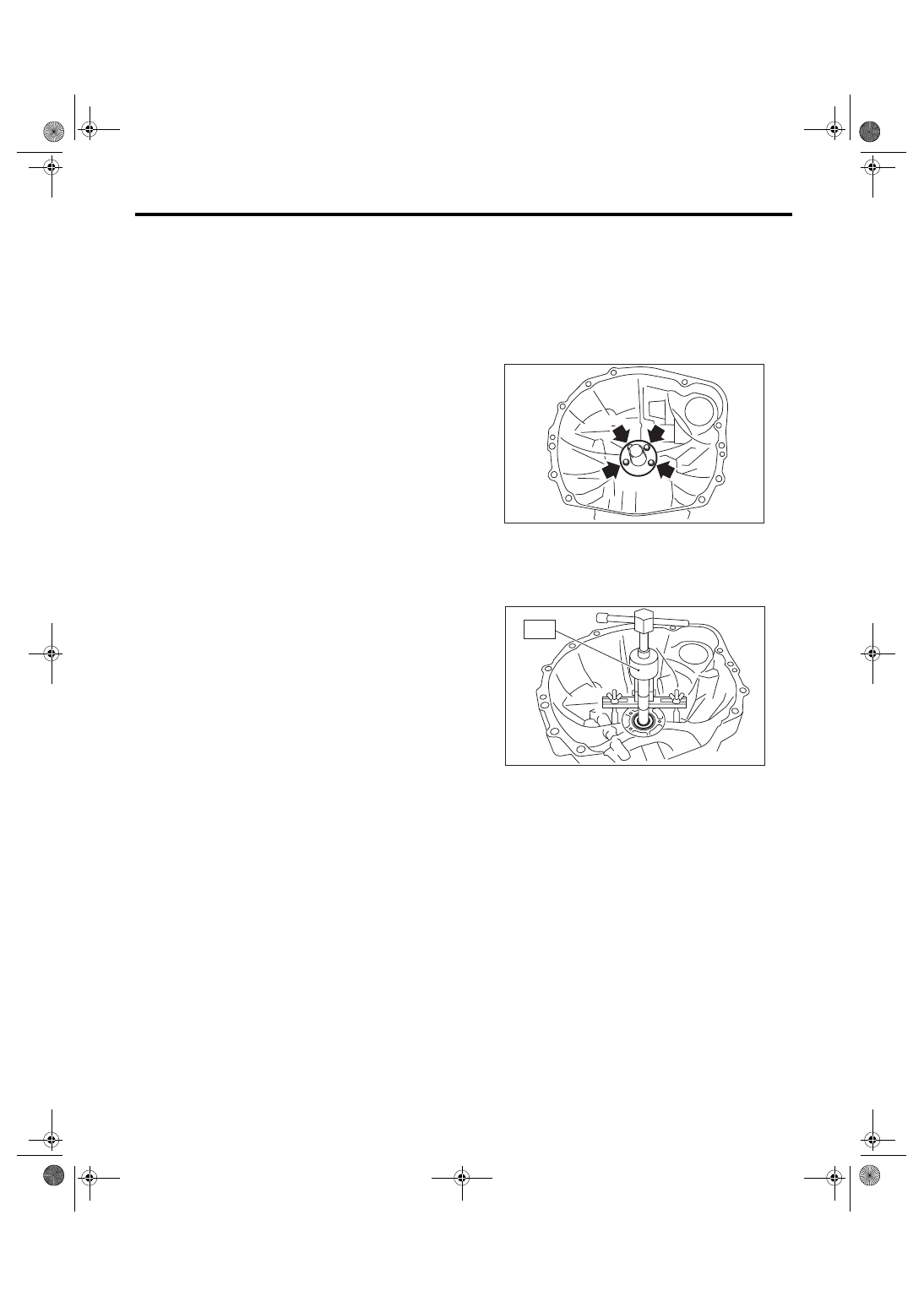
C: DISASSEMBLY
1) Remove the clutch release bearing guide.
2) Remove the oil seal.
ST
398527700
PULLER ASSY
NOTE:
Use a new oil seal.
MT-00717
MT-00718
ST
6MT-125
MANUAL TRANSMISSION AND DIFFERENTIAL
Clutch Housing
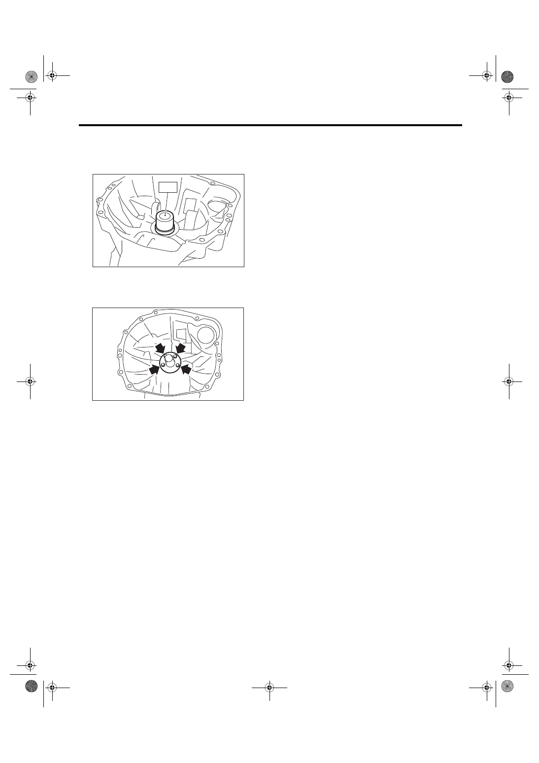
D: ASSEMBLY
1) Install the oil seal into clutch housing without
damaging.
ST
399513600
INSTALLER
2) Install the clutch release bearing guide.
Tightening torque:
6.4 N
⋅
m (0.65 kgf-m, 4.7 ft-lb)
E: INSPECTION
1) Check there is no damage or crack on clutch
housing. Replace the clutch housing with a new
one if there is excessive damage.
2) Check the clutch housing for gear oil leakage. If
there is oil leakage, repair or replace the leakage
part.
MT-00719
ST
MT-00717
6MT-126
MANUAL TRANSMISSION AND DIFFERENTIAL
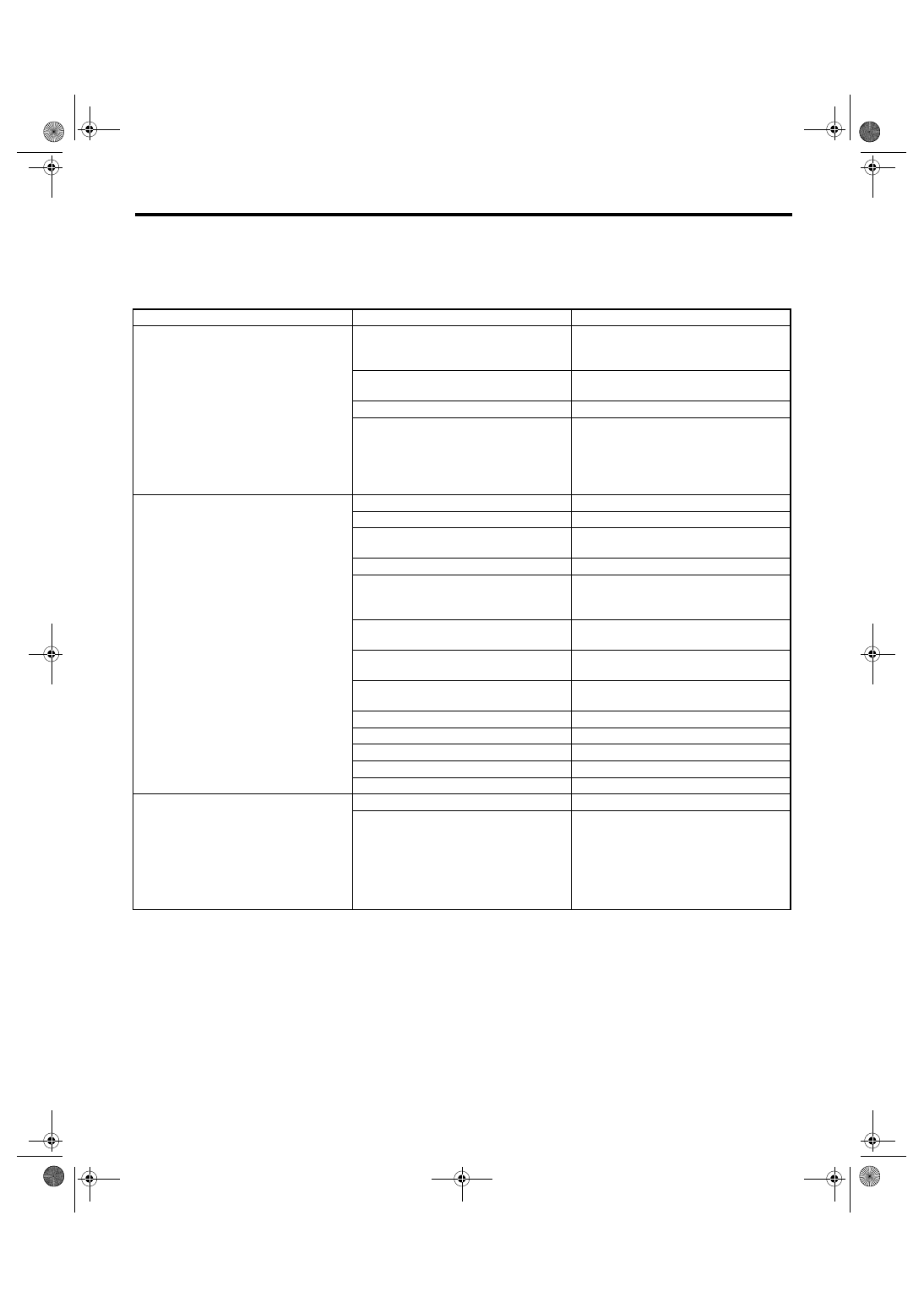
General Diagnostic Table
26.General Diagnostic Table
A: INSPECTION
1. MANUAL TRANSMISSION
Symptom
Possible cause
Corrective action
1. Gears are difficult to intermesh.
NOTE:
The cause for difficulty in shifting gears
can be classified into two kinds. One is de-
fective gear shift system and the other is
defective transmission. However, if the
operation is heavy and engagement of the
gears is difficult, defective clutch disen-
gagement may also be responsible.
Check whether the clutch is correctly
functioning, before checking the gear shift
system and transmission.
(a) Worn, damaged or burred chamfer of
internal spline of sleeve and reverse
driven gear
Replace.
(b) Worn, damaged or burred chamfer of
spline of gears
Replace.
(c) Worn or scratched bushings
Replace.
(d) Incorrect contact between synchro-
nizer ring and gear cone or wear
Correct or replace.
2. Gear slip-out.
• Gear slips out when coasting on rough
road.
• Gear slips out during acceleration.
(a) Defective pitching stopper
Adjust.
(b) Loose engine mounting bolts
Tighten or replace.
(c) Worn fork shifter, broken shifter fork
rail spring
Replace.
(d) Worn or damaged ball bearing
Replace.
(e) Excessive clearance between splines
of synchronizer hub and synchronizer
sleeve
Replace.
(f) Worn tooth step of synchronizer hub
(responsible for slip-out of 3rd gear)
Replace.
(g) Worn 1st driven gear, needle bearing
and race
Replace.
(h) Worn 2nd driven gear, needle bearing
and race
Replace.
(i) Worn 3rd drive gear and bushing
Replace.
(j) Worn 4th drive gear and bushing
Replace.
(k) Worn 5th drive gear and bushing
Replace.
(l) Worn 6th drive gear and bushing
Replace.
(m) Worn reverse idler gear and bushing
Replace.
3. Noise emits from the transmission.
NOTE:
If noise is heard when the vehicle is
parked with its engine idling and if a noise
ceases when the clutch is disengaged, it
may be considered that the noise comes
from the transmission.
(a) Insufficient or improper lubrication
Lubricate with specified oil or replace.
(b) Worn or damaged gears and bearings
NOTE:
If the trouble is only wear of the tooth sur-
faces, merely a high roaring noise will oc-
cur at high speeds, but if any part is
broken, rhythmical knocking sound will be
heard even at low speeds.
Replace.
Нет комментариевНе стесняйтесь поделиться с нами вашим ценным мнением.
Текст