Subaru Legacy (2005 year). Service manual — part 427

EN(H6DO)(diag)-21
ENGINE (DIAGNOSTICS)
Engine Condition Data
6. Engine Condition Data
A: ELECTRICAL SPECIFICATION
Measuring condition:
• After engine is warmed-up.
• Gear position is in N or P range.
• Turn the A/C to OFF.
• Turn all the accessory switches to OFF.
Remarks
Specifications
Engine load
1.6 — 2.9 (%): Idling
6.4 — 12.8 (%): 2,500 rpm racing
EN(H6DO)(diag)-22
ENGINE (DIAGNOSTICS)
Data Link Connector
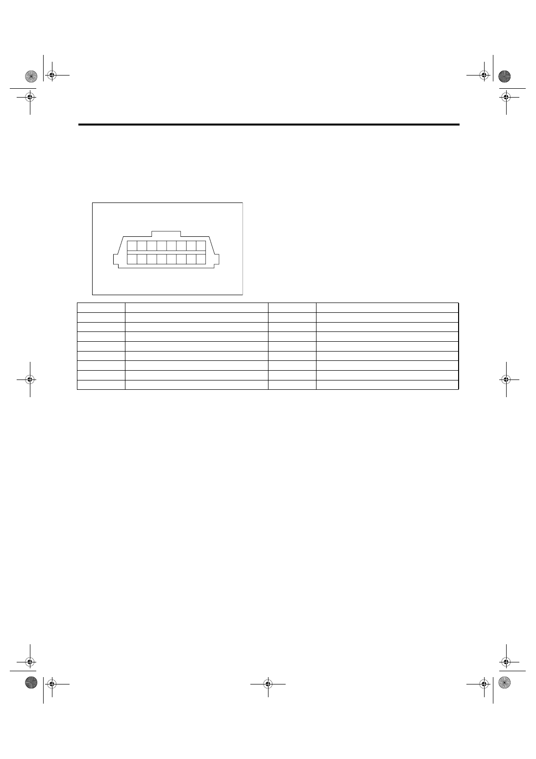
7. Data Link Connector
A: NOTE
This connector is used for connecting the Subaru Select Monitor.
CAUTION:
Do not connect any scan tools except Subaru Select Monitor or general scan tool because the circuit
for Subaru Select Monitor may be damaged.
EN-00037
1
2
3
4
5
7
6
8
9 10 11 12 13
15
14
16
Terminal No.
Remarks
Terminal No.
Remarks
1
Power supply
9
Empty
2
Empty
10
Subaru Select Monitor signal
3
Empty
11
Empty
4
Empty
12
Ground
5
Empty
13
Ground
6
Empty
14
Empty
7
Empty
15
Empty
8
Empty
16
Empty
EN(H6DO)(diag)-23
ENGINE (DIAGNOSTICS)
General Scan Tool
8. General Scan Tool
A: OPERATION
1. HOW TO USE GENERAL SCAN TOOL
1) Prepare a general scan tool required by SAE
J1978.
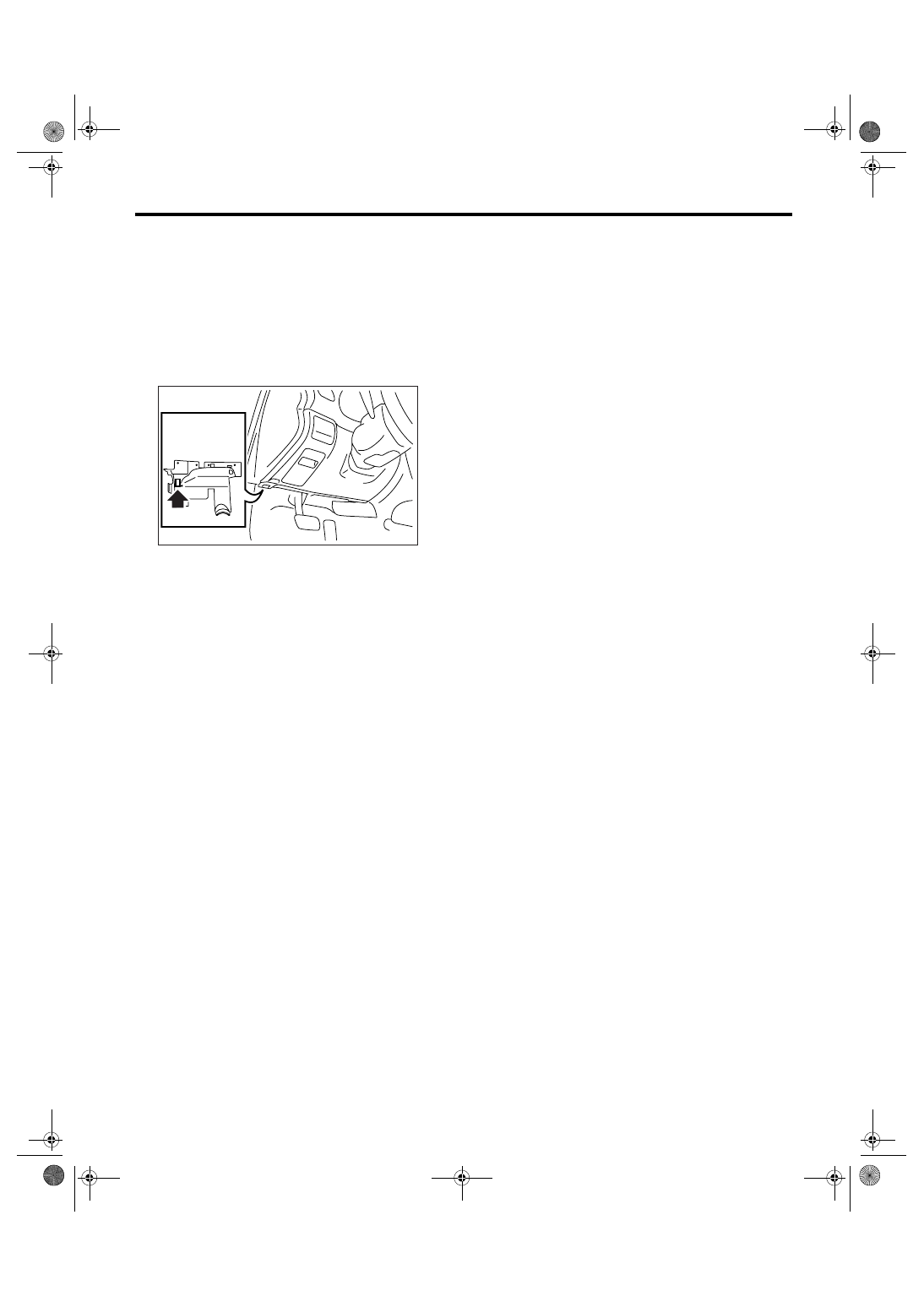
2) Connect the general scan tool to data link con-
nector located in the lower portion of the instrument
panel (on the driver’s side).
3) Using the general scan tool, call up DTC and
freeze frame data.
General scan tool functions consist of:
(1) MODE $01: Current powertrain diagnostic
data
(2) MODE $02: Powertrain freeze frame data
(3) MODE $03: Emission-related powertrain
DTC
(4) MODE $04: Clear/Reset emission-related
diagnostic information
Read out the data according to repair procedures.
(For detailed operation procedure, refer to the gen-
eral scan tool operation manual.)
NOTE:
For details concerning DTCs, refer to the List of Di-
agnostic Trouble Code (DTC). <Ref. to
EN(H6DO)(diag)-66, List of Diagnostic Trouble
Code (DTC).>
EN-02533

EN(H6DO)(diag)-24
ENGINE (DIAGNOSTICS)
General Scan Tool
2. MODE $01 (CURRENT POWERTRAIN DIAGNOSTIC DATA)
Refer to data denoting the current operating condition of analog input/output, digital input/output or the pow-
ertrain system.
A list of the support data and PID (Parameter Identification) codes are shown in the following table.
NOTE:
Refer to general scan tool manufacturer’s operation manual to access current powertrain diagnostic data
(MODE $01).
PID
Data
Unit of measure
01
Number of emission-related powertrain DTC and malfunction indicator light status
ON/OFF
03
Fuel system control status
—
04
Calculated engine load value
%
05
Engine coolant temperature
°C or °F
06
Short term fuel trim (bank 1)
%
07
Long term fuel trim (bank 1)
%
08
Short term fuel trim (bank 2)
%
09
Long term fuel trim (bank 2)
%
0B
Intake manifold absolute pressure
mmHg, kPa, inHg or
psig
0C
Engine revolution
rpm
0D
Vehicle speed
km/h or MPH
0E
Ignition timing advance
°
0F
Intake air temperature
°C or °F
10
Air flow rate from manifold absolute pressure sensor
g/s or lb/m
11
Throttle valve opening angle
%
13
Check whether oxygen sensor is installed.
—
15
Rear oxygen sensor output and control amout (Bank 1)
V and %
19
Rear oxygen sensor output and control amout (Bank 2)
V and %
1C
On-board diagnostic system
—
21
Driving distance after malfunction indicator light illuminates
km or miles
24
Oxygen sensor output voltage and short term fuel trim associated with oxygen sensor (bank
1)
V and %
28
Oxygen sensor output voltage and short term fuel trim associated with oxygen sensor (bank
2)
V and %
34
Front oxygen (A/F) sensor lambda valve and current (Bank 1)
— and mA
38
Front oxygen (A/F) sensor lambda valve and current (Bank 2)
— and mA
Нет комментариевНе стесняйтесь поделиться с нами вашим ценным мнением.
Текст