Subaru Legacy (2005 year). Service manual — part 430
EN(H6DO)(diag)-33
ENGINE (DIAGNOSTICS)
Read Diagnostic Trouble Code (DTC)
10.Read Diagnostic Trouble
Code (DTC)
A: OPERATION
1. SUBARU SELECT MONITOR (NORMAL
MODE)
1) On the «Main Menu» display screen, select the
{Each System Check} and press the [YES] key.
2) On the «System Selection Menu» display
screen, select the {Engine} and press the [YES]
key.
3) Press the [YES] key after the information of en-
gine type has been displayed.
4) On the «Engine Diagnosis» screen, select the
{DTC Display}, and then press the [YES] key.
5) On the «Diagnostic Code(s) Display» screen,
select the {Current Diagnostic Code(s)} or {History
Diagnostic Code(s)}, and then press the [YES] key.
NOTE:
• For detailed operation procedure, refer to the
SUBARU SELECT MONITOR OPERATION MAN-
UAL.
• For details concerning DTC, refer to “List of Diag-
nostic Trouble Code (DTC)”. <Ref. to
EN(H6DO)(diag)-66, List of Diagnostic Trouble
Code (DTC).>
2. SUBARU SELECT MONITOR (OBD
MODE)
1) On the «Main Menu» display screen, select the
{Each System Check} and press the [YES] key.
2) On the «System Selection Menu» display
screen, select the {Engine} and press the [YES]
key.
3) Press the [YES] key after the information of en-
gine type has been displayed.
4) On the «Engine Diagnosis» display screen, se-
lect the {OBD System} and press the [YES] key.
5) On the «OBD Menu» display screen, select the
{DTC Display} and press the [YES] key.
6) Make sure DTC is shown on the screen.
NOTE:
• For detailed operation procedure, refer to the
SUBARU SELECT MONITOR OPERATION MAN-
UAL.
• For details concerning DTC, refer to “List of Diag-
nostic Trouble Code (DTC)”. <Ref. to
EN(H6DO)(diag)-66, List of Diagnostic Trouble
Code (DTC).>
3. GENERAL SCAN TOOL
Refer to data denoting emission-related powertrain
DTC.
For details concerning DTC, refer to “List of Diag-
nostic Trouble Code (DTC)”. <Ref. to
EN(H6DO)(diag)-66, List of Diagnostic Trouble
Code (DTC).>
NOTE:
Refer to general scan tool manufacturer’s opera-
tion manual to access powertrain DTC (MODE
$03).
EN(H6DO)(diag)-34
ENGINE (DIAGNOSTICS)
Inspection Mode
11.Inspection Mode
A: PROCEDURE
When performing the diagnose without the “List of Diagnostic Trouble Code (DTC)”, refer the item of drive cy-
cle. <Ref. to EN(H6DO)(diag)-39, Drive Cycle.>
DTC
Item
On condition
P0011
Intake Camshaft Position-Timing Over-Advanced or System Performance
(Bank 1)
—
P0021
Intake Camshaft Position-Timing Over-Advanced or System Performance
(Bank 2)
—
P0031
HO2S Heater Control Circuit Low (Bank 1 Sensor 1)
—
P0032
HO2S Heater Control Circuit High (Bank 1 Sensor 1)
—
P0037
HO2S Heater Control Circuit Low (Bank 1 Sensor 2)
—
P0038
HO2S Heater Control Circuit High (Bank 1 Sensor 2)
—
P0051
HO2S Heater Control Circuit Low (Bank 2 Sensor 1)
—
P0052
HO2S Heater Control Circuit High (Bank 2 Sensor 1)
—
P0057
HO2S Heater Control Circuit Low (Bank 2 Sensor 2)
—
P0058
HO2S Heater Control Circuit High (Bank 2 Sensor 2)
—
P0077
Intake Valve Control Solenoid Circuit High (Bank 1)
—
P0083
Intake Valve Control Solenoid Circuit High (Bank 2)
—
P0102
Mass or Volume Air Flow Circuit Low Input
—
P0103
Mass or Volume Air Flow Circuit High Input
—
P0107
Manifold Absolute Pressure/Barometric Pressure Circuit Low Input
—
P0108
Manifold Absolute Pressure/Barometric Pressure Circuit High Input
—
P0112
Intake Air Temperature Sensor 1 Circuit Low
—
P0113
Intake Air Temperature Sensor 1 Circuit High
—
P0117
Engine Coolant Temperature Circuit Low
—
P0118
Engine Coolant Temperature Circuit High
—
P0122
Throttle/Pedal Position Sensor/Switch “A” Circuit Low
—
P0123
Throttle/Pedal Position Sensor/Switch “A” Circuit High
—
P0131
O2 Sensor Circuit Low Voltage (Bank 1 Sensor 1)
—
P0132
O2 Sensor Circuit High Voltage (Bank 1 Sensor 1)
—
P0137
O2 Sensor Circuit Low Voltage (Bank 1 Sensor 2)
—
P0138
O2 Sensor Circuit High Voltage (Bank 1 Sensor 2)
—
P0151
O2 Sensor Circuit Low Voltage (Bank 2 Sensor 1)
—
P0152
O2 Sensor Circuit High Voltage (Bank 2 Sensor 1)
—
P0157
O2 Sensor Circuit Low Voltage (Bank 2 Sensor 2)
—
P0158
O2 Sensor Circuit High Voltage (Bank 2 Sensor 2)
—
P0171
System Too Lean (Bank 1)
—
P0172
System Too Rich (Bank 1)
—
P0174
System Too Lean (Bank 2)
—
P0175
System Too Rich (Bank 2)
—
P0197
Engine Oil Temperature Sensor Low
—
P0198
Engine Oil Temperature Sensor High
—
P0222
Throttle/Pedal Position Sensor/Switch “B” Circuit Low
—
P0223
Throttle/Pedal Position Sensor/Switch “B” Circuit High
—
P0230
Fuel Pump Primary Circuit
—
P0327
Knock Sensor 1 Circuit Low (Bank 1 or Single Sensor)
—
P0328
Knock Sensor 1 Circuit High (Bank 1 or Single Sensor)
—
P0332
Knock Sensor 2 Circuit Low (Bank 2)
—
P0333
Knock Sensor 2 Circuit High (Bank 2)
—
P0335
Crankshaft Position Sensor “A” Circuit
—
P0340
Camshaft Position Sensor “A” Circuit (Bank 1 or Single Sensor)
—

EN(H6DO)(diag)-35
ENGINE (DIAGNOSTICS)
Inspection Mode
P0345
Camshaft Position Sensor “A” Circuit (Bank 2)
—
P0458
Evaporative Emission System Purge Control Valve Circuit Low
—
P0462
Fuel Level Sensor “A” Circuit Low
—
P0463
Fuel Level Sensor “A” Circuit High
—
P0500
Vehicle Speed Sensor “A”
—
P0512
Starter Request Circuit
—
P0519
Idle Air Control System Performance
—
P0600
Serial Communication Link
—
P0604
Internal Control Module Random Access Memory (RAM) Error
—
P0605
Internal Control Module Read Only Memory (ROM) Error
—
P0607
Control Module Performance
—
P0638
Throttle Actuator Control Range/Performance (Bank 1)
—
P0691
Fan 1 Control Circuit Low
—
P0692
Fan 1 Control Circuit High
—
P0700
Transmission Control System (MIL Request)
—
P0851
Park/Neutral Switch Input Circuit Low
—
P0852
Park/Neutral Switch Input Circuit High
—
P1160
Return Spring Failure
—
P1518
Starter Switch Circuit Low Input
—
P1560
Back-up Voltage Circuit Malfunction
—
P2088
Intake Camshaft Position Actuator Control Circuit Low (Bank 1)
—
P2089
Intake Camshaft Position Actuator Control Circuit High (Bank 1)
—
P2092
Intake Camshaft Position Actuator Control Circuit Low (Bank 2)
—
P2093
Intake Camshaft Position Actuator Control Circuit High (Bank 2)
—
P2101
Throttle Actuator Control Motor Circuit Range/Performance
—
P2102
Throttle Actuator Control Motor Circuit Low
—
P2103
Throttle Actuator Control Motor Circuit High
—
P2109
Throttle/Pedal Position Sensor “A” Minimum Stop Performance
—
P2122
Throttle/Pedal Position Sensor/Switch “D” Circuit Low Input
—
P2123
Throttle/Pedal Position Sensor/Switch “D” Circuit High Input
—
P2127
Throttle/Pedal Position Sensor/Switch “E” Circuit Low Input
—
P2128
Throttle/Pedal Position Sensor/Switch “E” Circuit High Input
—
P2135
Throttle/Pedal Position Sensor/Switch “A”/“B” Voltage Correlation
—
P2138
Throttle/Pedal Position Sensor/Switch “D”/“E” Voltage Correlation
—
P2503
Charging System Voltage Low
—
DTC
Item
On condition
EN(H6DO)(diag)-36
ENGINE (DIAGNOSTICS)
Inspection Mode
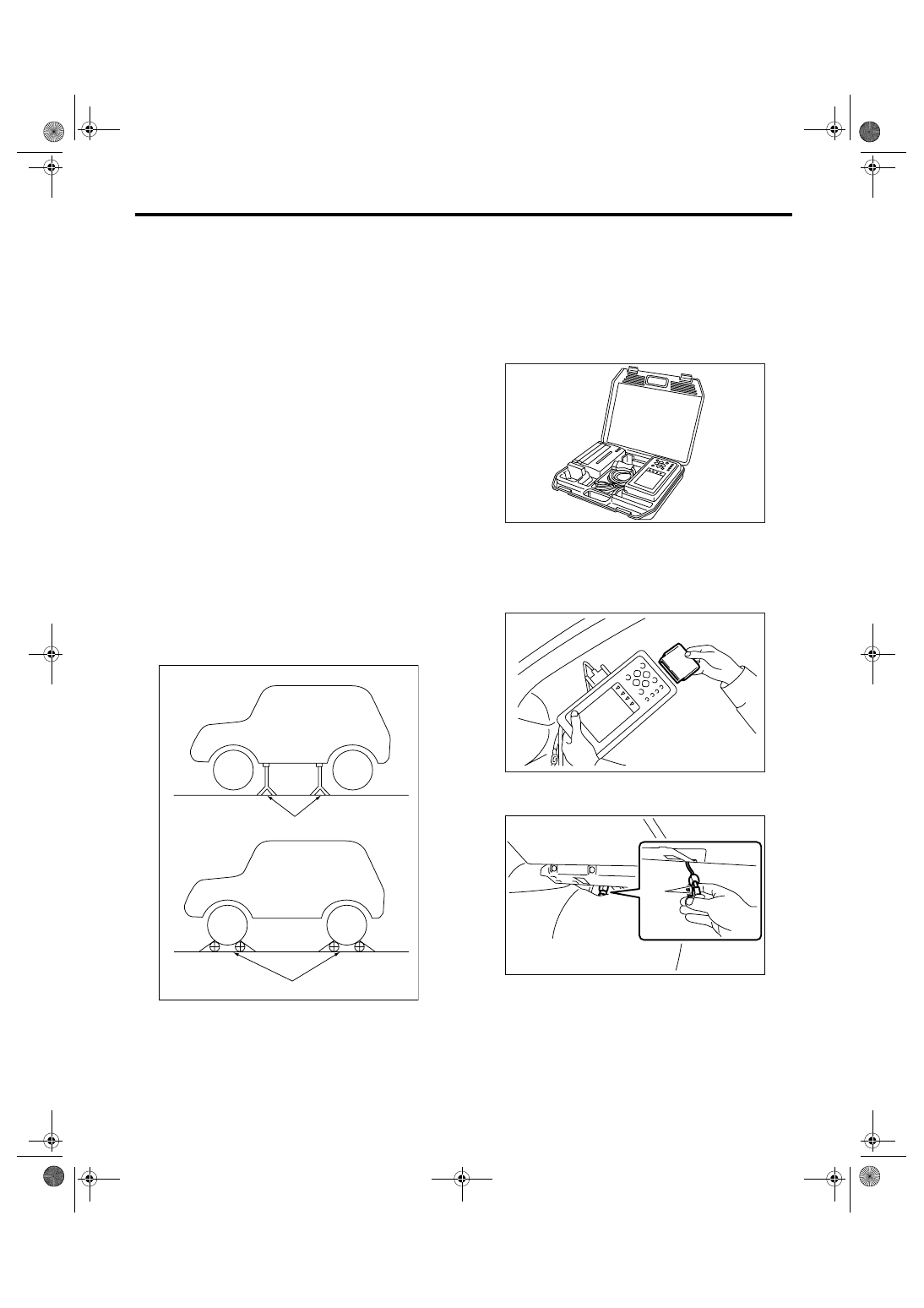
1. PREPARATION FOR THE INSPECTION
MODE
1) Check that the battery voltage is more than 12 V
and fuel remains half [20 — 40
2 (5.3 — 10.6 US
gal, 4.4 — 8.8 Imp gal)].
2) Lift-up the vehicle using a garage jack and place
it on rigid racks, or drive the vehicle onto free roll-
ers.
WARNING:
• Before lifting-up the vehicle, ensure parking
brakes are applied.
• Do not use a pantograph jack in place of a rig-
id rack.
• Secure a rope or wire to the front or rear tow-
ing hooks to prevent the lateral runout of front
wheels.
• Do not abruptly depress/release clutch pedal
or accelerator pedal during works even when
the engine is operating at low speeds since this
may cause vehicle to jump off free rollers.
• In order to prevent the vehicle from slipping
due to vibration, do not place any wooden
blocks or similar items between the rigid racks
and vehicle.
• Since the rear wheels will also rotate, do not
place anything near them. Also, make sure that
nobody goes in front of the vehicle.
2. SUBARU SELECT MONITOR
1) After clearing the memory, check for any remain-
ing unresolved trouble data. <Ref. to EN(H6DO)(di-
ag)-41, Clear Memory Mode.>
2) Idle the engine.
3) Prepare the Subaru Select Monitor kit. <Ref. to
EN(H6DO)(diag)-7, PREPARATION TOOL, Gen-
eral Description.>
4) Connect the diagnosis cable to Subaru Select
Monitor.
5) Insert the cartridge to Subaru Select Monitor.
<Ref. to EN(H6DO)(diag)-7, PREPARATION
TOOL, General Description.>
6) Connect the test mode connector (A) located at
the lower portion of glove box.
(A) Rigid racks
(B) Free rollers
EN-00041
(A)
(B)
EN-00038
EN-00039
PI-00201
(A)
Нет комментариевНе стесняйтесь поделиться с нами вашим ценным мнением.
Текст