Subaru Legacy (2005 year). Service manual — part 950
GW-7
GLASS/WINDOWS/MIRRORS
General Description
C: PREPARATION TOOL
1. SPECIAL TOOL
2. GENERAL TOOL
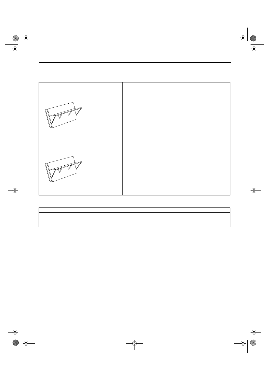
ILLUSTRATION
TOOL NUMBER
DESCRIPTION
REMARKS
61299AE000
SPACER
Used for adjusting the upper end position of front
door glass. (Glass thickness: 5 mm (0.197 in))
61299AE010
SPACER
Used for adjusting the upper end position of rear
door glass. (Glass thickness: 4 mm (0.157 in))
TOOL NAME
REMARKS
Circuit tester
Used for checking voltage and continuity.
Piano wire
Used for removing window glass.
Windshield glass knife
Used for removing window glass.
ST61299AE000
ST61299AE010
GW-8
GLASS/WINDOWS/MIRRORS
Power Window System
2. Power Window System
A: WIRING DIAGRAM
<Ref. to WI-295, Power Window System.>
B: INSPECTION
Symptom
Repair order
None of the power window operate.
(1) Fuse (SBF-5)
(2) Power window circuit breaker
(3) Power window relay
(4) Wiring harness
(5) Body integrated module
One window does not operate.
(1) Power window main switch
(2) Power window sub switch
(3) Power window motor
(4) Wiring harness
“Window Lock” does not operate.
Power window main switch
GW-9
GLASS/WINDOWS/MIRRORS
Power Window Control Switch
3. Power Window Control
Switch
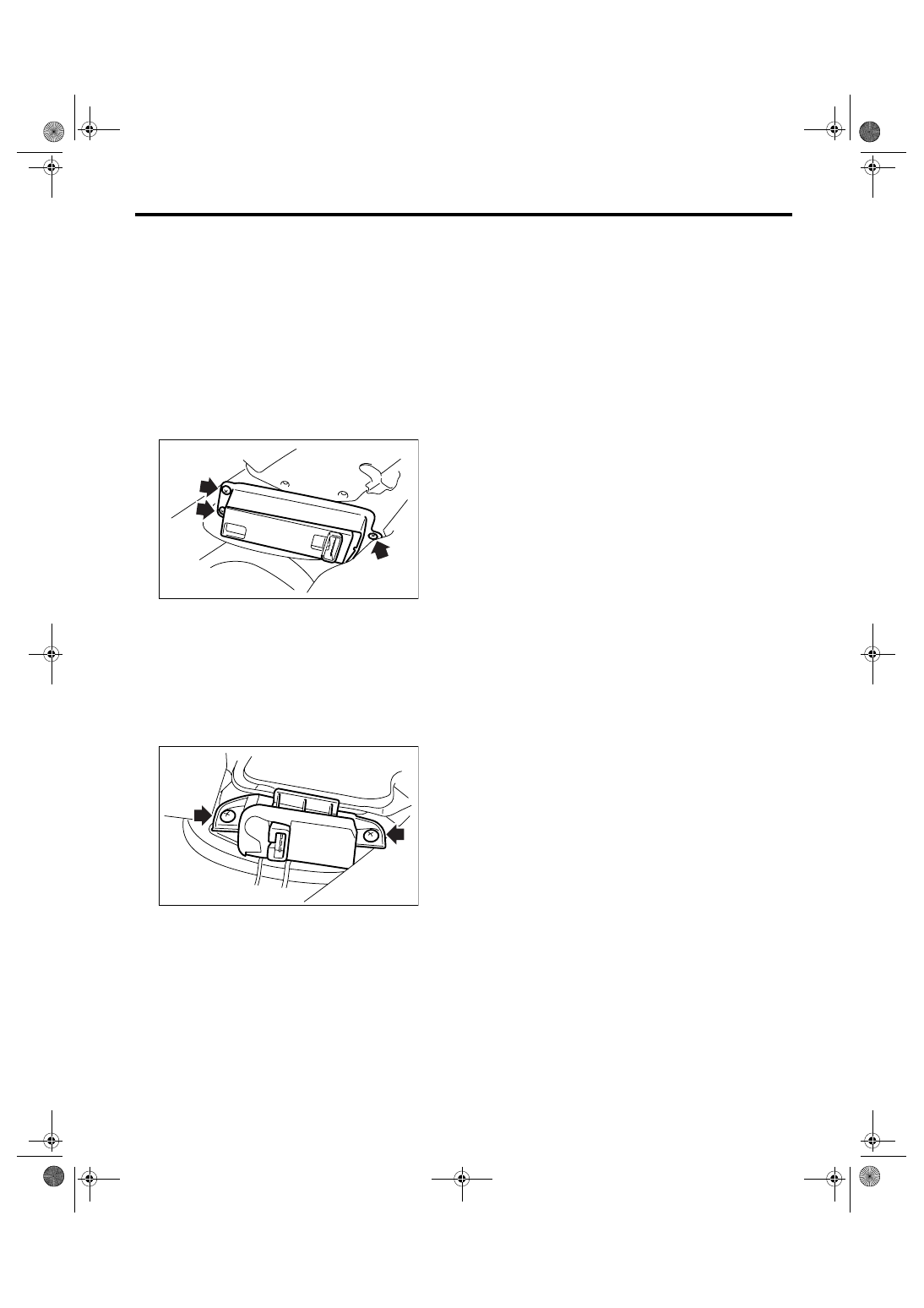
A: REMOVAL
1. MAIN SWITCH
1) Disconnect the ground cable from battery.
2) Remove the front door trim. <Ref. to EI-48, RE-
MOVAL, Door Trim.>
3) Disconnect the harness connector.
4) Remove the screws from the reverse side of
front door trim, and remove the power window main
switch.
2. SUB SWITCH
1) Disconnect the ground cable from battery.
2) Remove the door trim. <Ref. to EI-48, REMOV-
AL, Door Trim.>
3) Disconnect the connector.
4) Remove the screws from the reverse side of
door trim, and remove the power window sub
switch.
B: INSTALLATION
1. MAIN SWITCH
Install in the reverse order of removal.
2. SUB SWITCH
Install in the reverse order of removal.
GW-00387
GW-00388
GW-10
GLASS/WINDOWS/MIRRORS
Power Window Control Switch
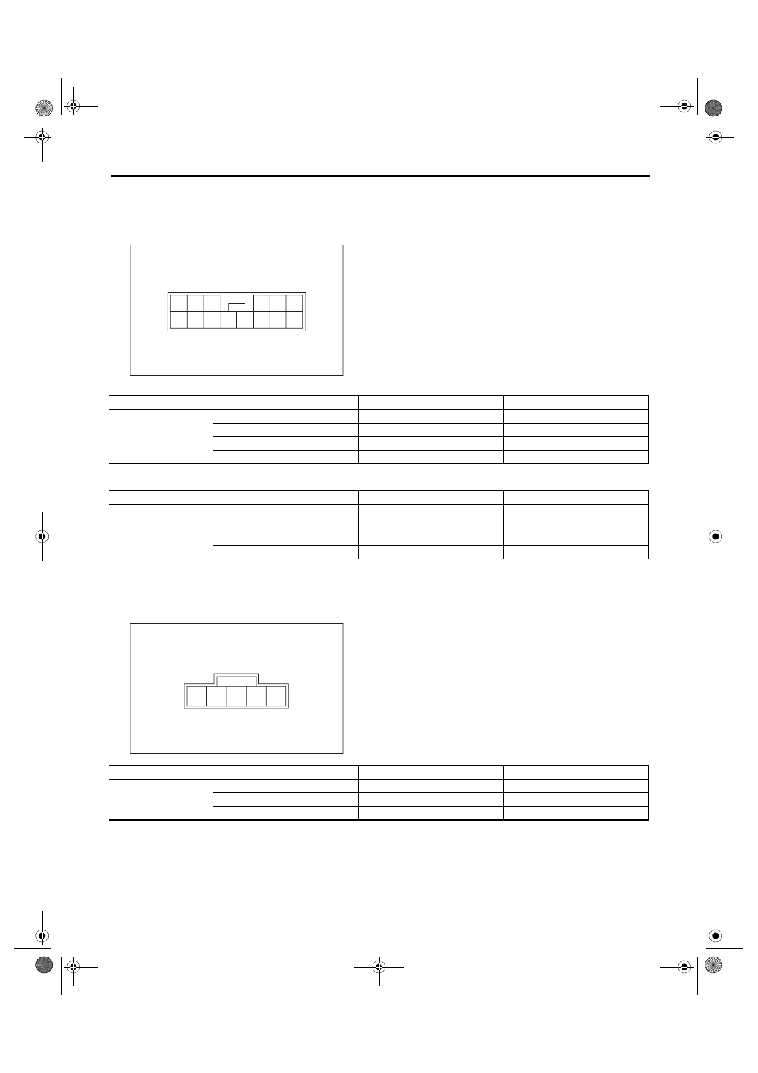
C: INSPECTION
1. MAIN SWITCH
Measure the resistance of switch.
• LHD model
• RHD model
Replace the main switch if faulty.
2. SUB SWITCH
Measure the resistance of switch.
Replace the sub switch if faulty.
GW-00406
1
2
3
4
5
6
7
8
9
10
11
12
13
14
Switch position
Terminal No.
Standard
Driver’s seat
AUTO UP
10 and 2, 7 and 1
Less than 1
Ω
UP
10 and 2, 7 and 1
Less than 1
Ω
DOWN
10 and 1, 7 and 2
Less than 1
Ω
AUTO DOWN
10 and 1, 7 and 2
Less than 1
Ω
Switch position
Terminal No.
Standard
Driver’s seat
AUTO UP
11 and 1, 14 and 2
Less than 1
Ω
UP
11 and 1, 14 and 2
Less than 1
Ω
DOWN
11 and 2, 14 and 1
Less than 1
Ω
AUTO DOWN
11 and 2, 14 and 1
Less than 1
Ω
GW-00407
1
2
3
4
5
Switch position
Terminal No.
Standard
Passenger’s seat and
rear seat
UP
2 and 3, 4 and 5
Less than 1
Ω
OFF
1 and 2, 4 and 5
Less than 1
Ω
DOWN
1 and 2, 3 and 4
Less than 1
Ω
Нет комментариевНе стесняйтесь поделиться с нами вашим ценным мнением.
Текст