Subaru Legacy (2005 year). Service manual — part 229
EN(H4SO 2.5)(diag)-201
ENGINE (DIAGNOSTICS)
Diagnostic Procedure with Diagnostic Trouble Code (DTC)
Step
Check
Yes
No
1
CHECK OPTION CODE.
Is the option code EC, EK, EH,
ER or K4?
Refer to EN(H4SO
2.0) section. <Ref.
to EN(H4SO
2.0)(diag)-64, List
of Diagnostic Trou-
ble Code (DTC).>
NOTE:
Fuel injection sys-
tem for KA and KS
model is the same
as 2.0 L model.
2
CHECK OPERATION OF STARTER MOTOR.
Turn the ignition switch to START.
NOTE:
• For AT model, set the selector lever in the
“P” or “N” range.
• For MT model, depress the clutch pedal.
Does the starter motor oper-
ate?
Repair the har-
ness and connec-
tor.
NOTE:
In this case, repair
the following:
• Open or ground
short circuit of har-
ness between
ECM and starter
motor connector
• Poor contact in
ECM connector
Check the starter
motor circuit. <Ref.
to EN(H4SO
2.5)(diag)-54,
STARTER
MOTOR CIRCUIT,
Diagnostics for
Engine Starting
Failure.>
EN(H4SO 2.5)(diag)-202
ENGINE (DIAGNOSTICS)
Diagnostic Procedure with Diagnostic Trouble Code (DTC)
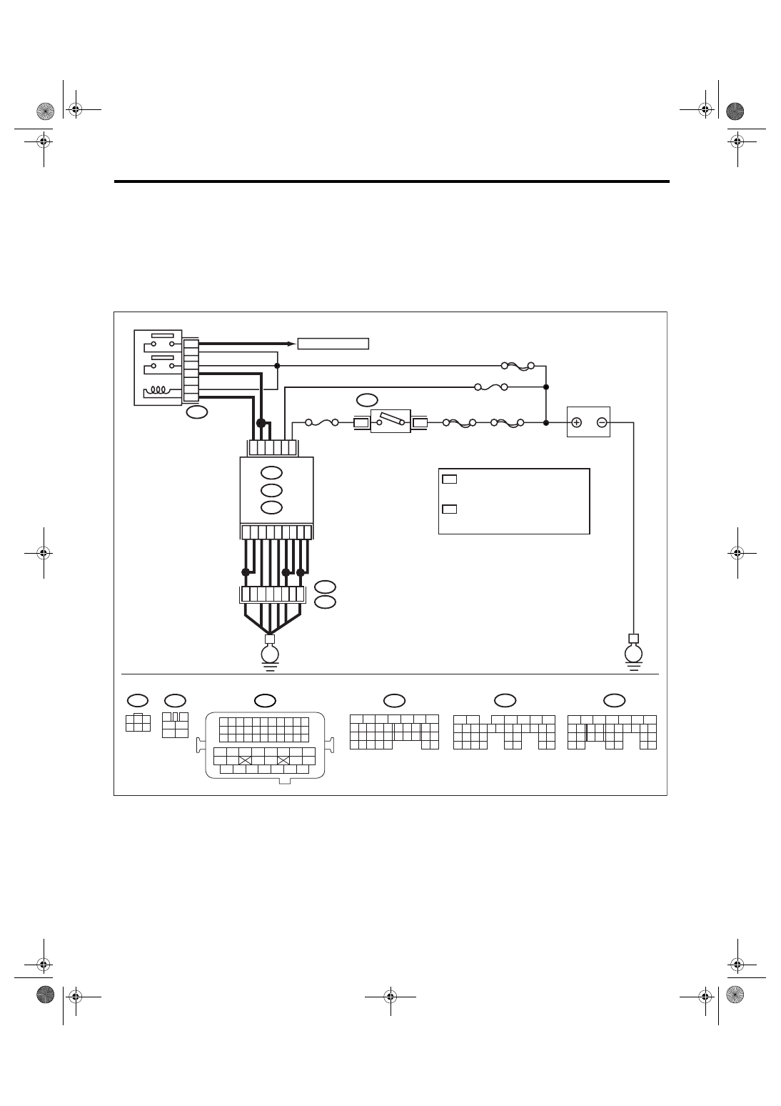
BO:DTC P1560 BACK-UP VOLTAGE CIRCUIT MALFUNCTION
DTC DETECTING CONDITION:
Immediately at fault recognition
CAUTION:
After repair or replacement of faulty parts, conduct Clear Memory Mode <Ref. to EN(H4SO 2.5)(diag)-
40, Clear Memory Mode.> and Inspection Mode <Ref. to EN(H4SO 2.5)(diag)-33, Inspection Mode.>.
WIRING DIAGRAM:
• EC, EK, EH, ER and K4 model
• KA and KS model
NOTE:
Fuel injection system for KA and KS model is the same as 2.0 L model. Refer to EN(H4SO 2.0) section.
EN-03511
SBF-6
MAIN SBF
SBF-7
B72
B6
B5
A6
D2
A7
B12
D3
D7
D1
B19
No.12
B47
E2
B21
6
5
E
E
3
6
B134
B135
A:
D: B137
B:
B4
52
37
36
34
47
3
4
1
2
5
6
B47
No.13
B1
35
B134
5
6
7
8
2
1
9
4
3
10
24
22 23
25
11 12 13 14 15
26 27
28
16 17
18 19 20 21
33 34
29
32
30 31
B135
5
6
7
8
2
1
9
4
3
10
24
22 23
25
11 12 13 14 15
26 27
28
16 17 18 19
20 21
29 30 31
32 33
34 35
B137
5
6
7
8
2
1
9
4
3
10
22 23
11 12 13 14 15
24 25
26
16 17
18 19 20 21
27
28 29
30 31
B21
1 2 3 4
12 13 14 15
5 6 7 8
16 17 18 19
9 10 11
20 21 22
23 24 25 26 27 28 29 30 31 32 33
35
34
37
36
39
38
41
40
43
42
44
45
47
46
49
48
51
50
53
52
54
B72
1
3
4 5 6
2
A:
B:
D:
1
2
1
*
2
*
4
3
ECM
1
*
2
*
MAIN RELAY
TO IGNITION COIL
IGNITION
SWITCH
BATTERY
LHD WITH IMMOBILIZER: D16
LHD WITHOUT IMMOBILIZER: D17
RHD : D16
LHD WITH IMMOBILIZER: D14
LHD WITHOUT IMMOBILIZER: D15
RHD : D14

EN(H4SO 2.5)(diag)-203
ENGINE (DIAGNOSTICS)
Diagnostic Procedure with Diagnostic Trouble Code (DTC)
Step
Check
Yes
No
1
CHECK OPTION CODE.
Is the option code EC, EK, EH,
ER or K4?
Refer to EN(H4SO
2.0) section. <Ref.
to EN(H4SO
2.0)(diag)-64, List
of Diagnostic Trou-
ble Code (DTC).>
NOTE:
Fuel injection sys-
tem for KA and KS
model is the same
as 2.0 L model.
2
CHECK INPUT SIGNAL OF ECM.
1) Turn the ignition switch to OFF.
2) Measure the voltage between ECM and
chassis ground.
Connector & terminal
(B135) No. 19 (+) — Chassis ground (
−
):
Is the voltage more than 10 V? Repair the poor
contact in ECM
connector.
3
CHECK HARNESS BETWEEN ECM AND
MAIN FUSE BOX CONNECTOR.
1) Disconnect the connector from ECM.
2) Measure the resistance of harness
between ECM and chassis ground.
Connector & terminal
(B135) No. 19 — Chassis ground:
Is the resistance less than 10
Ω?
Repair the ground
short circuit of har-
ness between
ECM connector
and battery termi-
nal.
4
CHECK FUSE No. 13.
Is the fuse blown out?
Replace the fuse.
Repair the har-
ness and connec-
tor.
NOTE:
In this case, repair
the following:
• Open circuit of
harness between
ECM and battery
• Poor contact in
ECM connector
• Poor contact in
battery terminal
EN(H4SO 2.5)(diag)-204
ENGINE (DIAGNOSTICS)
Diagnostic Procedure with Diagnostic Trouble Code (DTC)
BP:DTC P2004 INTAKE MANIFOLD RUNNER CONTROL STUCK OPEN (BANK
1)
DTC DETECTING CONDITION:
Immediately at fault recognition
CAUTION:
After repair or replacement of faulty parts, conduct Clear Memory Mode <Ref. to EN(H4SO 2.5)(diag)-
40, Clear Memory Mode.> and Inspection Mode <Ref. to EN(H4SO 2.5)(diag)-33, Inspection Mode.>.
BQ:DTC P2005 INTAKE MANIFOLD RUNNER CONTROL STUCK OPEN (BANK
2)
DTC DETECTING CONDITION:
Immediately at fault recognition
CAUTION:
After repair or replacement of faulty parts, conduct Clear Memory Mode <Ref. to EN(H4SO 2.5)(diag)-
40, Clear Memory Mode.> and Inspection Mode <Ref. to EN(H4SO 2.5)(diag)-33, Inspection Mode.>.
Step
Check
Yes
No
1
CHECK ANY OTHER DTC ON DISPLAY.
Is any other DTC displayed?
Inspect the rele-
vant DTC using
“List of Diagnostic
Trouble Code
(DTC)”. <Ref. to
EN(H4SO
2.5)(diag)-69, List
of Diagnostic Trou-
ble Code (DTC).>
2
CHECK TUMBLE GENERATOR VALVE RH.
1) Remove the tumble generator valve assem-
bly.
2) Check the tumble generator valve body.
Does the tumble generator
valve move smoothly? (No dirt,
no foreign material clogged)
Replace the tum-
ble generator valve
assembly. <Ref. to
FU(H4SO 2.5)-28,
Tumble Generator
Valve Assembly.>
Clean tumble gen-
erator valve.
Step
Check
Yes
No
1
CHECK ANY OTHER DTC ON DISPLAY.
Is any other DTC displayed?
Inspect the rele-
vant DTC using
“List of Diagnostic
Trouble Code
(DTC)”. <Ref. to
EN(H4SO
2.5)(diag)-69, List
of Diagnostic Trou-
ble Code (DTC).>
2
CHECK TUMBLE GENERATOR VALVE LH.
1) Remove the tumble generator valve assem-
bly.
2) Check the tumble generator valve body.
Does the tumble generator
valve move smoothly? (No dirt,
no foreign material clogged)
Replace the tum-
ble generator valve
assembly. <Ref. to
FU(H4SO 2.5)-28,
Tumble Generator
Valve Assembly.>
Clean the tumble
generator valve.
Нет комментариевНе стесняйтесь поделиться с нами вашим ценным мнением.
Текст