Subaru Legacy (2005 year). Service manual — part 398
ME(H6DO)-67
MECHANICAL
Cylinder Block
B: INSTALLATION
1) After setting the cylinder block to ST, install the
crankshaft bearing.
ST
18232AA000
ENGINE STAND
NOTE:
Remove oil on the mating surface of bearing and
cylinder block before installation. Apply a coat of
engine oil to crankshaft pins.
2) Position the crankshaft and connecting rod on
the #2, #4 and #6 cylinder block.
3) Apply liquid gasket to the mating surface of #1,
#3 and #5 cylinder block, and position it on #2, #4
and #6 cylinder block.
Liquid gasket:
THREE BOND 1215 (Part No. 004403007)
NOTE:
Do not allow liquid gasket to run over to O-ring
grooves, oil passages, bearing grooves, etc.
Applying liquid gasket diameter:
1.0
±
0.2 mm (0.039
±
0.008 in)
4) Apply a coat of engine oil to washers and bolt
threads.
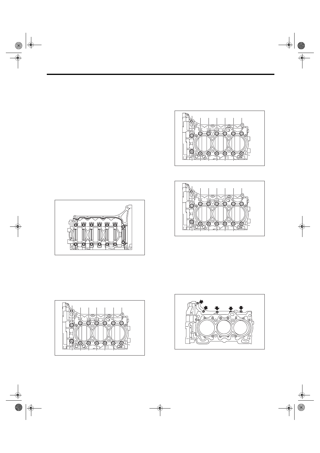
5) Tighten all bolts in the numerical order as shown
in the figure.
Tightening torque:
(1) — (11), (13): 25 N
⋅
m (2.5 kgf-m, 18.4 ft-lb)
(12), (14): 20 N
⋅
m (2.0 kgf-m, 14 ft-lb)
6) Retighten all bolts in the numerical order as
shown in the figure.
Tightening torque:
(1) — (11), (13): 25 N
⋅
m (2.5 kgf-m, 18.4 ft-lb)
(12), (14): 20 N
⋅
m (2.0 kgf-m, 14 ft-lb)
7) Tighten all bolts 90 — 110
° in the numerical or-
der as shown in the figure.
8) Install the upper bolt to cylinder block.
Tightening torque:
25 N
⋅
m (2.5 kgf-m, 18.4 ft-lb)
NOTE:
Remove the liquid gasket which is running over to
sealing surface between cylinder block and rear
chain cover, cylinder block and oil pan upper, after
tightening the bolts which combine the cylinder
block.
9) Install the rear oil seal using ST1 and ST2.
ST1
499597100
CRANKSHAFT OIL SEAL
GUIDE
ST2
499587200
CRANKSHAFT OIL SEAL IN-
STALLER
ME-00567
(1)
(6)
(8)
(3)
(9)
(2)
(4)
(5)
(7)
(10)
(11)
(12)
(13)
(14)
ME-00568
(1)
(6)
(8)
(3)
(9)
(2)
(4)
(5)
(7)
(10)
(11)
(12)
(13)
(14)
ME-00568
(1)
(6)
(8)
(3)
(9)
(2)
(4)
(5)
(7)
(10)
(11)
(12)
(13)
(14)
ME-00568
ME-00569
ME(H6DO)-68
MECHANICAL
Cylinder Block
NOTE:
Apply engine oil to the pressing-in portion.
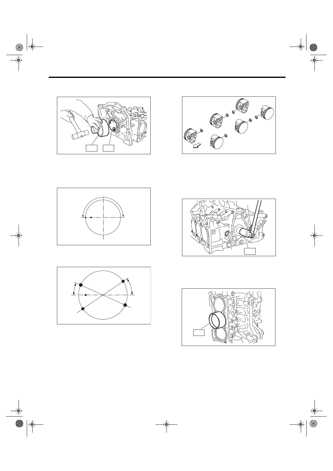
10) Position the top ring gap at (A) in the figure.
11) Position the second ring gap at (B).
12) Position the upper rail gap at (C) in the figure.
13) Position the expander gap at (D) in the figure.
14) Position the lower rail gap at (E) in the figure.
CAUTION:
• Ensure ring gaps do not face the same direc-
tion.
• Ensure ring gaps are not within the piston
skirt area.
• Ensure R mark faces to top side of piston.
15) Install the snap ring.
Install snap rings in the piston holes located oppo-
site to the service holes in cylinder block, when po-
sitioning all pistons in the corresponding cylinders.
NOTE:
Use new snap rings.
16) Installation of piston.
(1) Using the ST1, turn the crankshaft so that
#3 and #4 connecting rods small end are set on
the service hole (A).
ST1
18252AA000 CRANKSHAFT SOCKET
(2) Apply a thin coat of engine oil to piston and
cylinder.
(3) Using the ST2, press-fit the piston into cylin-
der.
ST2
18254AA000 PISTON GUIDE
(A) Rear oil seal
(B) Drive plate installation bolt
ST2
ST1
(A)
(B)
ME-00570
180˚
(A)
(B)
ME-02066
25˚
35˚
(C)
(D)
(E)
ME-02067
(A) Forward
(A)
#1
#2
#3
#4
#5
#6
ME-00573
ST1
(A)
(A)
ME-00574
ST2
ME-00576
ME(H6DO)-69
MECHANICAL
Cylinder Block
NOTE:
Let the piston front mark (A) face towards the front
of engine.
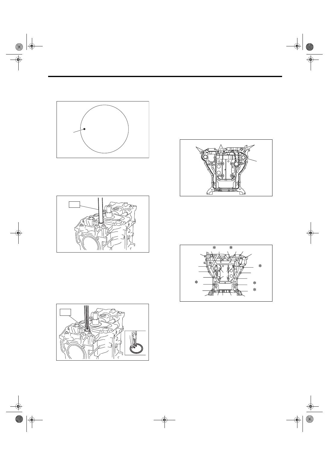
17) Installing piston pin.
(1) Apply a coat of engine oil to ST3 before in-
sertion, and then insert it into the service hole to
align piston pin hole with connecting rod small
end.
ST3
18253AA000 PISTON GUIDE
(2) Apply a coat of engine oil to piston pin, and
insert the piston pin into piston and connecting
rod through service hole.
(3) Using the ST4, install the snap ring.
ST4
18233AA000 PISTON PIN SNAP RING PLI-
ERS
NOTE:
Use new snap rings.
(4) Similarly install the #1, #2, #5 and #6 pis-
tons.
18) Install the service hole plug and O-ring.
NOTE:
Use a new O-ring.
19) Apply liquid gasket to the mating surface of oil
pan upper.
Liquid gasket:
THREE BOND 1280B (Part No. K0877YA018)
Applying liquid gasket diameter:
Full line part
3.0
±
1.0 mm (0.12
±
0.04 in)
Broken line part
1.0 mm (0.04 in)
NOTE:
Use a new O-ring.
20) Temporarily tighten the oil pan upper.
NOTE:
Do not install the bolts in wrong place.
(A)
ME-02076
ST3
ME-00577
ST4
ME-00564
(A) O-ring
(A) M8
× 40
(B) M8
× 65
(C) M8
× 85
(D) M8
× 130
(E) M8
× 24
*: Coating
ME-02068
(A)
(A)
(A)
(A)
ME-02069
(D)
(E)
(A)
(A)
(A)
(A)
(A)
(A)
(A)
(E)
(A)
(A)
(A)
(C)
(B)
(A)
(D)
(A)
(A)
(A)
(A)
(A)
(B)
ME(H6DO)-70
MECHANICAL
Cylinder Block
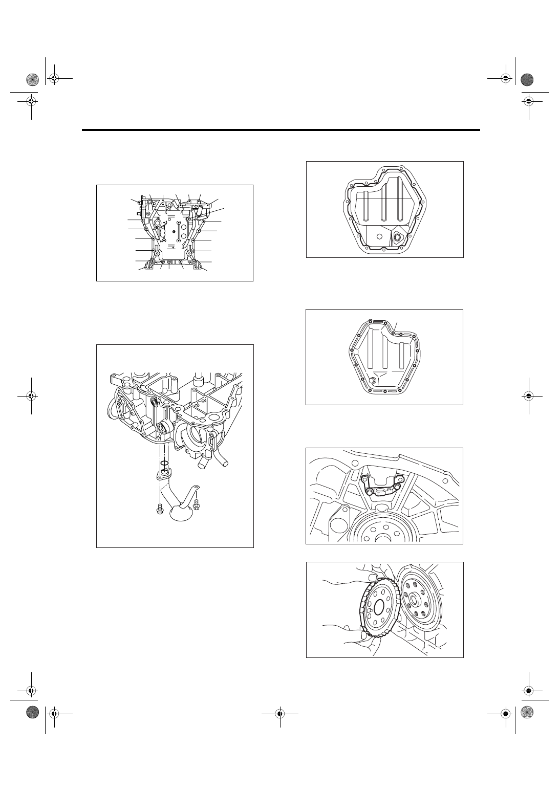
21) Tighten the oil pan upper installing bolts in the
numerical order as shown in the figure.
Tightening torque:
18 N
⋅
m (1.8 kgf-m, 13.3 ft-lb)
22) Install the oil strainer.
Tightening torque:
6.4 N
⋅
m (0.65 kgf-m, 4.7 ft-lb)
NOTE:
Use a new O-ring.
23) Apply liquid gasket to the matching surface of
oil pan lower.
Liquid gasket:
THREE BOND 1280B (Part No. K0877YA018)
Applying liquid gasket diameter:
5.0
±
1.0 mm (0.20
±
0.04 in)
24) Tighten the oil pan lower installing bolts in the
numerical order as shown in the figure.
Tightening torque:
6.4 N
⋅
m (0.65 kgf-m, 4.7 ft-lb)
25) Install the crankshaft sensor bracket.
Tightening torque:
6.4 N
⋅
m (0.65 kgf-m, 4.7 ft-lb)
26) Install the crankshaft sensor plate.
ME-02070
(19)
(14)
(12)
(16)
(24)
(22)
(27)
(25)
(21)
(17)
(13)
(11)
(15)
(23)
(26)
(20)
(18)
(7)
(6)
(9)
(8) (10)
(5)
(3)
(4)
(1)
(2)
LU-02108
ME-00581
(1)
(2)
(3)
(4)
(5)
(6)
(7)
(8)
(9)
(10)
(11)
(12)
(13)
(14)
(15)
ME-00582
ME-00559
ME-00558
Нет комментариевНе стесняйтесь поделиться с нами вашим ценным мнением.
Текст