Subaru Legacy (2005 year). Service manual — part 735
DI-47
DIFFERENTIALS
Rear Differential (VA-type)
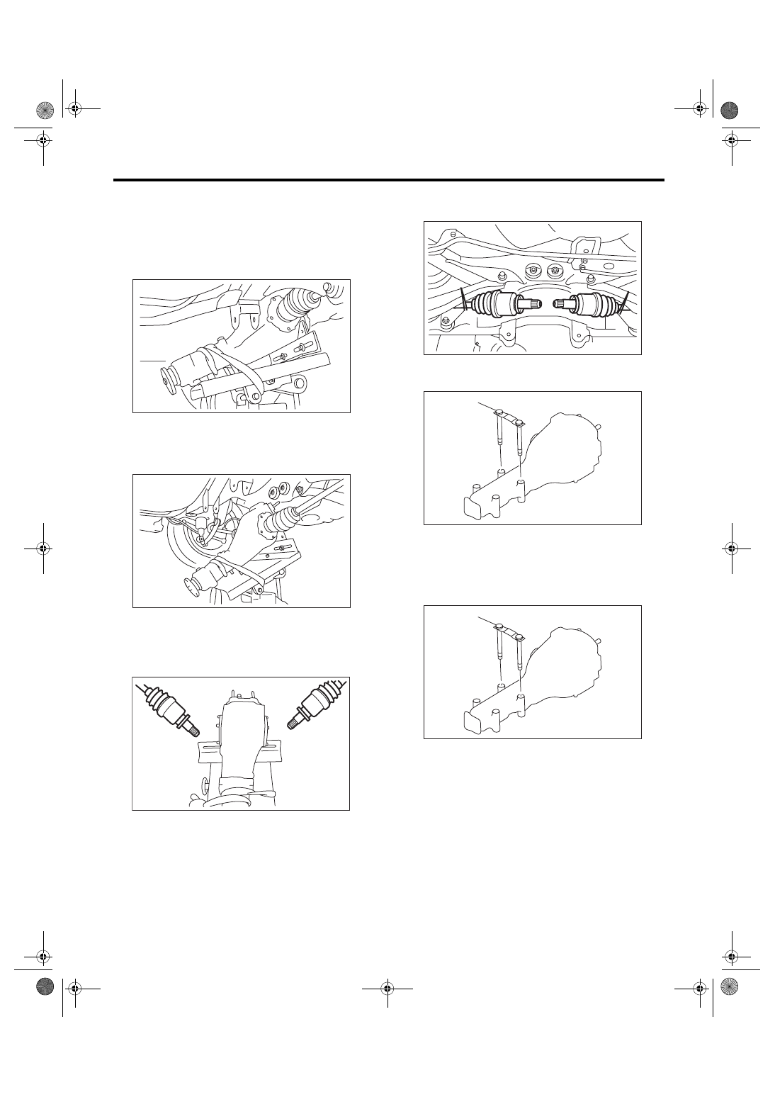
18) Remove the rear differential stud bolt from rear
crossmember bushing.
NOTE:
When removing the stud bolt, carefully adjust the
angle and location of transmission jack and jack
stand, if necessary.
19) Lower the transmission jack stand after remov-
ing the rear differential stud bolt from rear cross-
member. Rear drive shaft should not come into
contact with lateral link bolt.
20) Pull out the axle shaft from rear differential.
NOTE:
If it is difficult to remove the axle shaft from rear dif-
ferential, remove it using tire lever.
21) Lower the transmission jack.
22) Secure the rear drive shaft to lateral link using
wire.
23) Remove the rear differential member plate from
rear differential.
B: INSTALLATION
1) Insert the rear differential member plate into rear
differential.
2) Set the rear differential to transmission jack.
NOTE:
Secure the rear differential to transmission jack us-
ing band.
DI-00400
DI-00392
DI-00276
(A) Rear differential member plate
(A) Rear differential member plate
DI-00277
DI-00359
(A)
DI-00359
(A)
DI-48
DIFFERENTIALS
Rear Differential (VA-type)
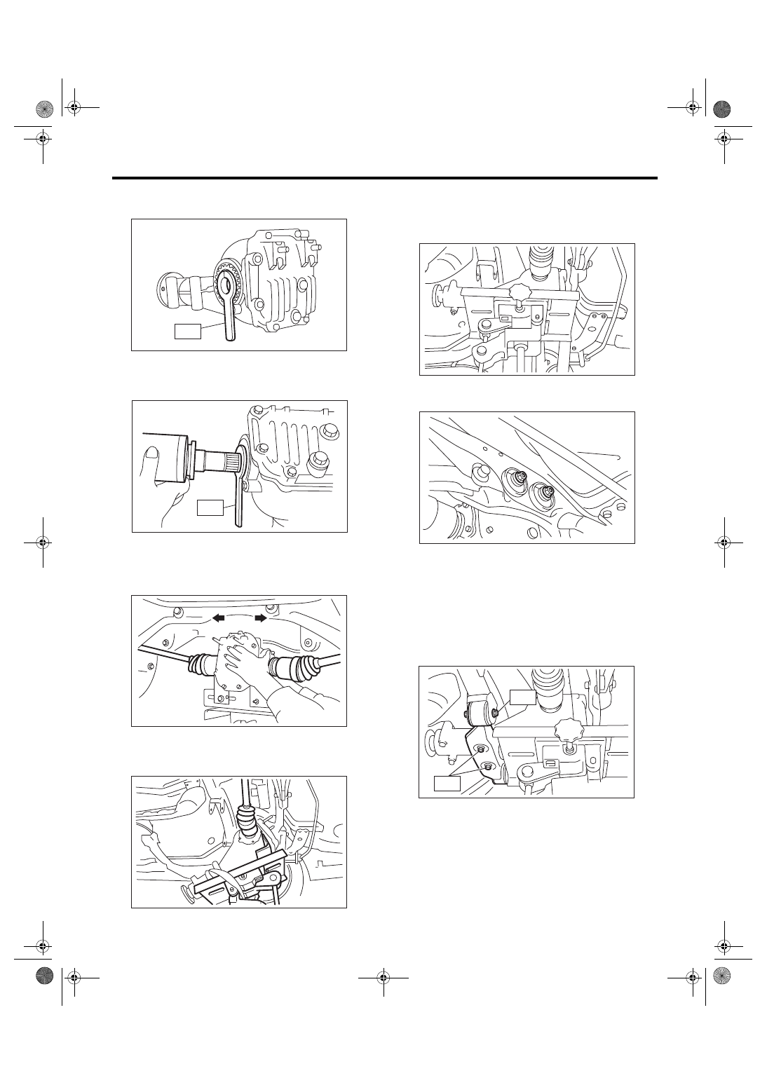
3) Install the ST to rear differential.
ST
28099PA090
OIL SEAL PROTECTOR
4) Insert the spline shaft until the spline portion
comes inside the side oil seal.
ST
28099PA090
OIL SEAL PROTECTOR
5) Remove ST from rear differential.
ST
28099PA090
OIL SEAL PROTECTOR
6) Push the rear differential to insert the axle shaft
into rear differential.
7) Adjust the transmission jack, if necessary, and
insert the rear differential stud bolt into rear cross-
member bushing properly.
8) After inserting the rear differential stud bolt into
rear crossmember bushing, lift up the transmission
jack and align the rear differential to the height of
rear differential.
9) Tighten a new self-locking nut temporarily to rear
crossmember.
10) Remove the band from rear differential. Lift up
the rear differential until the rear differential is left
from the transmission jack.
11) Install the rear differential front member with a
new self-locking nut.
Tightening torque:
T1: 52 N
⋅
m (5.3 kgf-m, 38 ft-lb)
T2: 110 N
⋅
m (11.2 kgf-m, 81 ft-lb)
DI-00300
ST
DI-00289
ST
DI-00281
DI-00393
DI-00283
DI-00269
DI-00284
T2
T1
DI-49
DIFFERENTIALS
Rear Differential (VA-type)
12) Tighten the self-locking nut.
Tightening torque:
70 N
⋅
m (7.1 kgf-m, 51 ft-lb)
13) Lower the transmission jack.
14) Install the propeller shaft.
<Ref. to DS-11, INSTALLATION, Propeller Shaft.>
15) Install the heat shield cover.
16) Install the rear exhaust pipe and muffler.
C: DISASSEMBLY
1. VA1-TYPE
To detect the real cause of trouble, inspect the fol-
lowing items before disassembling.
• Tooth contact and backlash between hypoid driv-
en gear and drive pinion
• Hypoid driven gear runout on its back surface
• Total preload of drive pinion
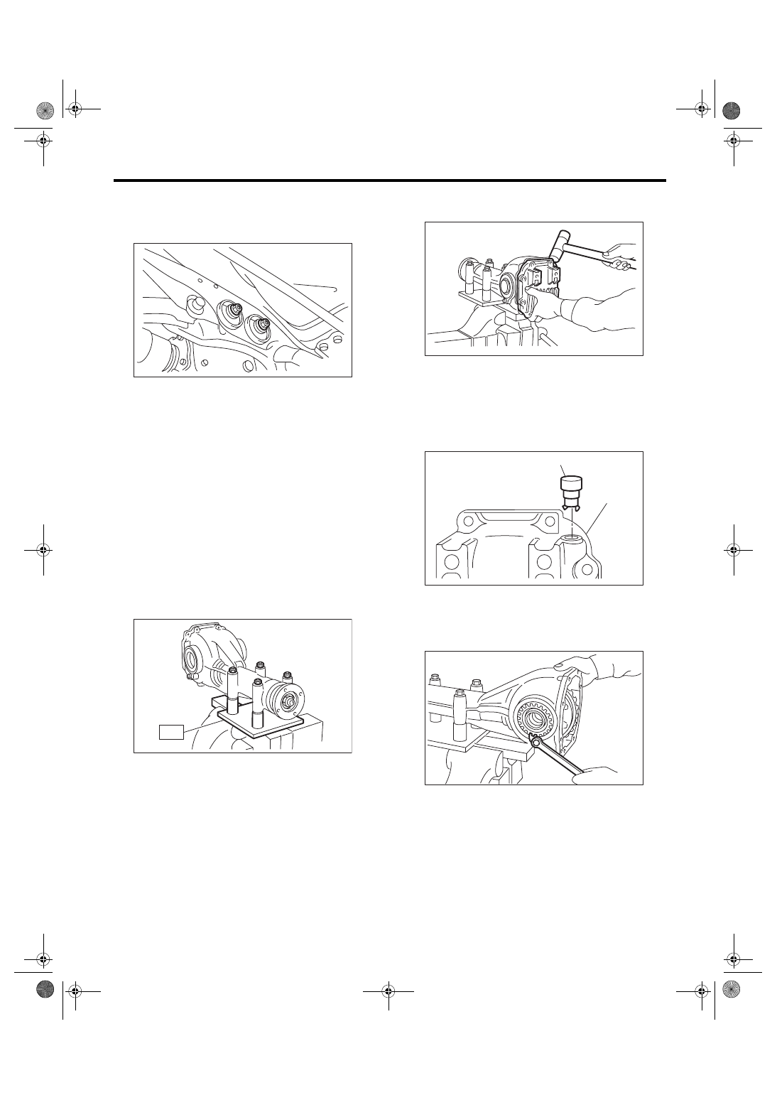
1) Set the ST on vise and install the differential as-
sembly to ST.
ST
398217700
ATTACHMENT SET
2) Drain the gear oil by removing plug.
3) Remove the rear cover by loosening retaining
bolts.
4) Remove the air breather cap.
NOTE:
• Do not attempt to remove the air breather cap
unless necessary.
• When removing the air breather cap, replace it
with a new one.
5) Remove the lock plate RH and LH.
DI-00269
ST
DI-00129
(A) Air breather cap
(B) Rear cover
DI-00130
(A)
(B)
DI-00131
DI-00132
DI-50
DIFFERENTIALS
Rear Differential (VA-type)
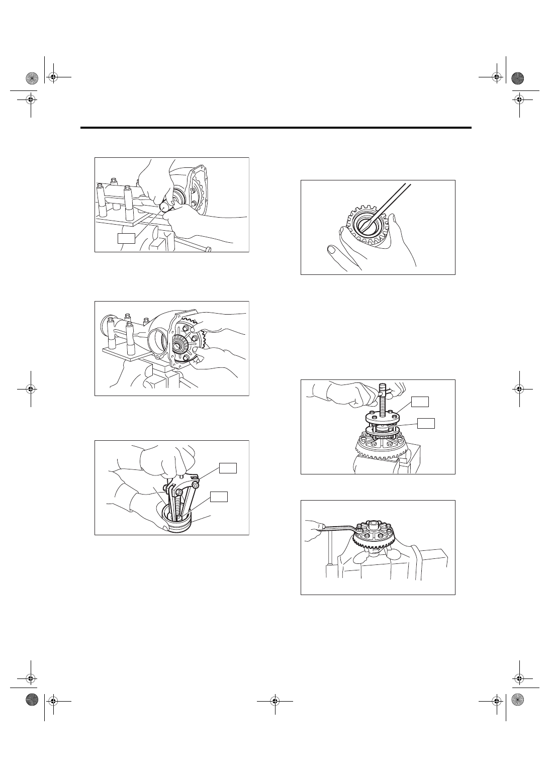
6) Remove the holder RH and LH with ST.
ST
499785500
WRENCH ASSY
7) Pull out the differential assembly from differential
carrier.
NOTE:
Be careful not to hit the teeth against the case.
8) Remove the bearing race from holder RH and
LH with ST1 and ST2.
ST1
499705401
PULLER ASSY
ST2
499705404
SEAT
9) Remove the oil seal from holder RH and LH us-
ing screwdriver.
NOTE:
Perform this operation only when replacing oil seal.
10) Extract the bearing cone with ST1 and ST2.
NOTE:
• Do not attempt to disassemble the parts unless
necessary.
• Set the puller so that its claws catch the edge of
the bearing cone.
• Never mix up the bearing races RH and LH and
cones.
ST1
899524100
PULLER SET
ST2
399520105
SEAT
11) Remove the hypoid driven gear by loosening
hypoid driven gear bolts.
(A) Bearing race
(B) Holder
DI-00133
ST
DI-00134
ST1
ST2
(B)
(A)
DI-00135
DI-00136
ST2
ST1
DI-00137
DI-00068
Нет комментариевНе стесняйтесь поделиться с нами вашим ценным мнением.
Текст