Subaru Legacy (2005 year). Service manual — part 514
4AT-37
AUTOMATIC TRANSMISSION
Line Pressure Test
7. Line Pressure Test
A: MEASUREMENT
NOTE:
If the clutch or the brake shows a sign of slippage or
shifting sensation is not correct, the line pressure
should be checked.
• Excessive shocks during up-shift may be due to
the line pressure being too high.
• Slippage or inability to operate the vehicle may,
in most cases, be due to loss of oil pressure for the
operation of the clutch, brake or control valve.
1) Line pressure measurement (under no load):
(1) Before measuring line pressure, jack-up all
the wheels.
(2) Maintain the temperature of ATF at approx.
70 — 80
°C (158 — 176°F) during measurement.
(ATF will reach the temperature mentioned
above after idling the engine for approx. 30 min-
utes with the select lever in “N” or “P”.)
2) Line pressure measurement (under heavy load):
(1) Before measuring line pressure, apply both
the foot and parking brakes with all wheels
chocked (Same as for “stall” test conditions).
(2) Measure the line pressure when the select
lever is in “R” or 2nd of manual mode with en-
gine under stall conditions.
(3) Measure the line pressure within 5 seconds
after shifting the select lever to each position. (If
the line pressure needs to be measured again,
allow the engine to idle and cool it down more
than 1 minute.)
(4) Maintain the ATF temperature at approx. 70
— 80
°C (158 — 176°F) during measurement.
(ATF will reach the temperature mentioned
above after idling the engine for approx. 30 min-
utes with the select lever in “N” or “P”.)
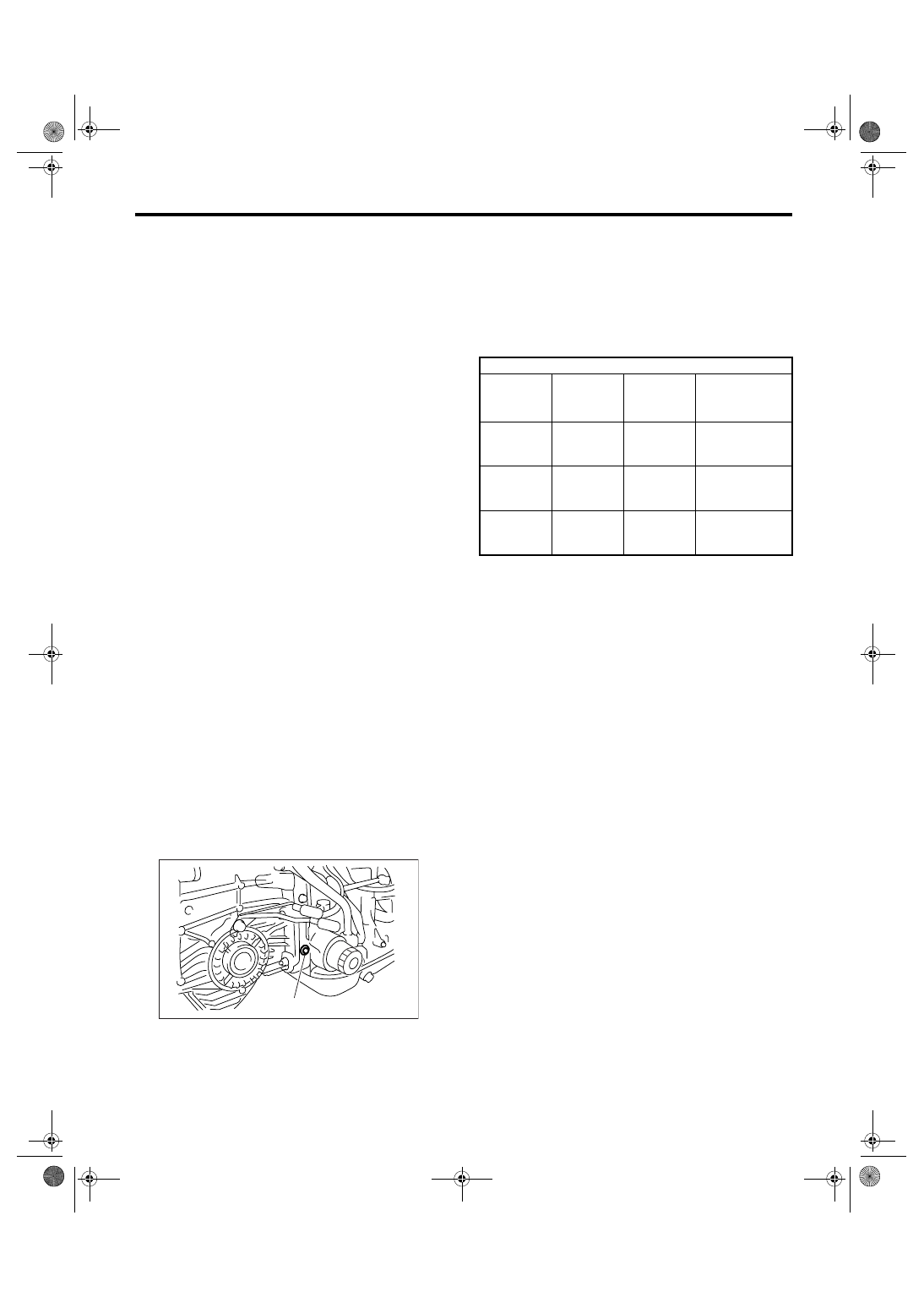
3) Remove the test plug and install the ST instead.
ST
498897200
OIL PRESSURE GAUGE
ADAPTER
4) Connect the ST1 with ST2.
ST1
498897200
OIL PRESSURE GAUGE
ADAPTER
ST2
498575400
OIL PRESSURE GAUGE
ASSY
5) Check for duty ratio changes by adjusting the ac-
celeration pedal position using Subaru Select Mon-
itor.
(A) Test plug
AT-03205
(A)
Specified line pressure
Range posi-
tion
Line pres-
sure duty
ratio (%)
Throttle
valve angle
Line pressure
kPa (kgf/cm
2
,
psi)
Manual
mode (2nd)
25 — 35
Full open
1,000 — 1,300
(10.2 — 13.3,
145 — 189)
R
15 — 25
Full open
1,500 — 1,850
(15.3 — 18.9,
217 — 268)
D
35 — 43
Full closed
500 — 800
(5.1 — 8.2, 73 —
116)
4AT-38
AUTOMATIC TRANSMISSION
Transfer Clutch Pressure Test
8. Transfer Clutch Pressure
Test
A: INSPECTION
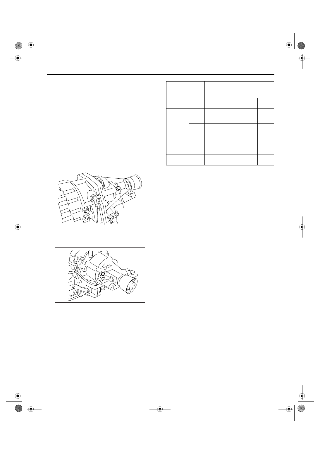
Check the transfer clutch pressure in accordance
with the following chart in the same manner as with
line pressure. <Ref. to 4AT-37, Line Pressure
Test.>
ST
498897700
OIL PRESSURE ADAPTER
SET
ST
498575400
OIL PRESSURE GAUGE
ASSY
NOTE:
• Before setting in FWD mode, install the spare
fuse on FWD mode switch. (MP-T model)
• MP-T model
• VTD model
• If no oil pressure is produced or if it does not
change in AWD mode, the control valve body may
be malfunctioning. If the oil pressure is produced in
FWD mode, the same defective as AWD mode oc-
curs.
(A) Test plug
(A) Test plug
AT-00021
( A )
AT-00022
(A)
Range
position
ON
Duty
ratio
(%)
Accelera-
tion pedal
position
(%)
Standard transfer clutch
pressure
kPa (kgf/cm
2
, psi)
AWD mode
FWD
mode
Manual
mode
(2nd)
95
Fully
opened
(100)
1,000 — 1,200
(10.2 — 12.2,
145 — 174)
—
60
Adjust
ON Duty
ratio to
60%.
500 — 700
(5.1 — 7.1, 73
— 102)
—
—
Fully
closed (0)
—
0 (0, 0)
N or P
5
Fully
closed (0)
0
—
4AT-39
AUTOMATIC TRANSMISSION
Automatic Transmission Assembly
9. Automatic Transmission As-
sembly
A: REMOVAL
1) Set the vehicle on a lift.
2) Fully open the front hood and support with hood
stay.
3) Disconnect the ground cable from battery.
4) Remove the air intake duct.
<Ref. to IN(H4SO 2.0)-8, REMOVAL, Air Intake
Duct.>
5) Remove the air intake chamber.
<Ref. to IN(H4SO 2.0)-7, REMOVAL, Air Intake
Chamber.>
6) Remove the air cleaner case stay.
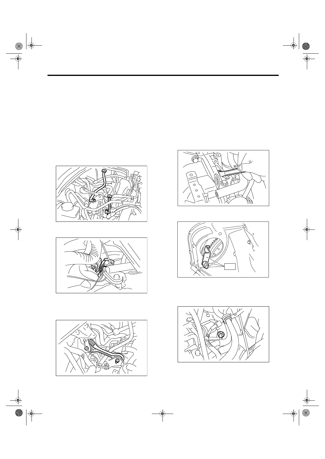
7) Disconnect the following connectors.
(1) Transmission harness connectors
(2) Transmission ground terminal
8) Remove the starter.
<Ref. to SC(H4SO 2.0)-6, REMOVAL, Starter.>
9) Remove the pitching stopper.
10) Separate the torque converter clutch from drive
plate.
(1) Remove the V-belt covers.
(2) Remove the service hole plug.
(3) Remove the bolts which hold torque con-
verter clutch to drive plate.
(4) Insert the wrench to crank pulley bolt, and
then remove all the bolts with gradually rotating
crank pulley.
CAUTION:
Be careful not to drop bolts into torque convert-
er clutch housing.
11) Install the ST to converter case.
ST
498277200
STOPPER SET
12) Remove the ATF level gauge.
NOTE:
Plug the opening to prevent entry of foreign parti-
cles into transmission fluid.
13) Remove the throttle body. <Ref. to FU(H4SO
2.0)-10, REMOVAL, Throttle Body.>
AT-01327
AT-01328
AT-01329
AT-00102
AT-00804
ST
AT-01330
4AT-40
AUTOMATIC TRANSMISSION
Automatic Transmission Assembly
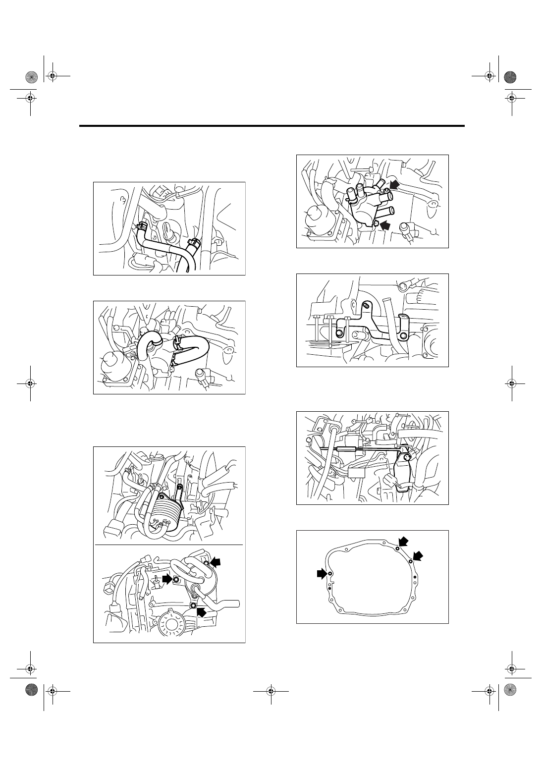
14) Drain engine coolant approx. 2
2 (2.1 US qt,
1.8 Imp qt). (Model with ATF cooler with warmer
function)
15) Disconnect the ATF cooler inlet and outlet hos-
es from ATF cooler pipes.
16) Disconnect each hose from warmer cock as-
sembly.
17) Remove the ATF cooler with warmer function
from transmission body, and then secure it to vehi-
cle body by wire, etc. Select the place not to pre-
vent transmission from being replaced. (Model with
ATF cooler with warmer function)
18) Remove the warmer cock assembly. (Model
with ATF cooler with warmer function)
19) Remove the bracket of warmer cock assembly.
(Model with ATF cooler with warmer function)
20) Remove the pitching stopper bracket.
21) Set the ST.
ST
41099AC000 ENGINE SUPPORT ASSEM-
BLY
22) Remove the bolts which install upper side of
transmission to engine.
23) Lift up the vehicle.
24) Remove the under cover.
AT-02171
AT-02163
AT-03199
AT-02165
AT-02166
AT-02167
ST
AT-00106
Нет комментариевНе стесняйтесь поделиться с нами вашим ценным мнением.
Текст