Subaru Legacy (2005 year). Service manual — part 813
VDC(diag)-117
VEHICLE DYNAMICS CONTROL (VDC) (DIAGNOSTICS)
Diagnostic Procedure with Diagnostic Trouble Code (DTC)
10
CHECK YAW RATE & LATERAL G SENSOR.
1) Turn the ignition switch to OFF.
2) Connect all the connectors.
3) Turn the ignition switch to ON.
4) Measure the voltage between VDCCM&H/
U connector terminals.
Connector & terminal
(B310) No. 1 (+) — No. 16 (
−
):
Is the voltage 2.1 — 2.9 V?
Replace the yaw
rate & lateral G
sensor.
11
CHECK YAW RATE & LATERAL G SENSOR.
1) Turn the ignition switch to ON.
2) Check the signal pattern of oscilloscope
between VDCCM&H/U connector terminals.
<Ref. to VDC(diag)-15, WAVEFORM, MEA-
SUREMENT, Control Module I/O Signal.>
Connector & terminal
(B310) No. 2 — No. 16:
(B310) No. 28 — No. 16:
Is the oscilloscope pattern the
same waveform as shown in
the figure?
Replace the yaw
rate & lateral G
sensor.
12
CHECK YAW RATE & LATERAL G SENSOR.
1) Turn the ignition switch to OFF.
2) Connect all the connectors.
3) Perform the clear memory mode.
4) Perform the inspection mode.
5) Read the DTC.
Is the same DTC displayed?
13
CHECK VDCCM&H/U.
1) Turn the ignition switch to OFF.
2) Replace the yaw rate & lateral G sensor.
3) Perform the clear memory mode.
4) Perform the inspection mode.
5) Read the DTC.
Is the same DTC displayed?
Replace the
VDCCM&H/U.
<Ref. to VDC-7,
VDC Control Mod-
ule and Hydraulic
Control Unit
(VDCCM&H/U).>
14
CHECK YAW RATE & LATERAL G SENSOR.
1) Turn the ignition switch to OFF.
2) Connect all the connectors.
3) Perform the clear memory mode.
4) Perform the inspection mode.
5) Read the DTC.
Is the same DTC displayed?
Replace the
VDCCM&H/U.
<Ref. to VDC-7,
VDC Control Mod-
ule and Hydraulic
Control Unit
(VDCCM&H/U).>
15
CHECK OTHER DTC DETECTION.
Is any other DTC displayed?
Perform the diag-
nosis according to
DTC.
Temporary poor
contact occurs.
16
CHECK OTHER DTC DETECTION.
Is any other DTC displayed?
Perform the diag-
nosis according to
DTC.
Malfunction is
found in original
yaw rate & lateral
G sensor.
Step
Check
Yes
No
VDC(diag)-118
VEHICLE DYNAMICS CONTROL (VDC) (DIAGNOSTICS)
Diagnostic Procedure with Diagnostic Trouble Code (DTC)
BB:DTC C0073 EXCESSIVE AMOUNT OF LATERAL G SENSOR OUTPUT OFF-
SET
NOTE:
For the diagnostic procedure, refer to DTC C0073. <Ref. to VDC(diag)-119, DTC C0073 EXCESSIVE LAT-
ERAL G SENSOR OUTPUT, Diagnostic Procedure with Diagnostic Trouble Code (DTC).>
BC:DTC C0073 LATERAL G SENSOR OUTPUT
NOTE:
For the diagnostic procedure, refer to DTC C0073. <Ref. to VDC(diag)-119, DTC C0073 EXCESSIVE LAT-
ERAL G SENSOR OUTPUT, Diagnostic Procedure with Diagnostic Trouble Code (DTC).>
BD:DTC C0073 EXCESSIVE VARIATION AMOUNT OF LATERAL G SENSOR
OUTPUT
NOTE:
For the diagnostic procedure, refer to DTC C0073. <Ref. to VDC(diag)-119, DTC C0073 EXCESSIVE LAT-
ERAL G SENSOR OUTPUT, Diagnostic Procedure with Diagnostic Trouble Code (DTC).>
VDC(diag)-119
VEHICLE DYNAMICS CONTROL (VDC) (DIAGNOSTICS)
Diagnostic Procedure with Diagnostic Trouble Code (DTC)
BE:DTC C0073 EXCESSIVE LATERAL G SENSOR OUTPUT
DTC DETECTING CONDITION:
Defective lateral G sensor
TROUBLE SYMPTOM:
VDC does not operate.
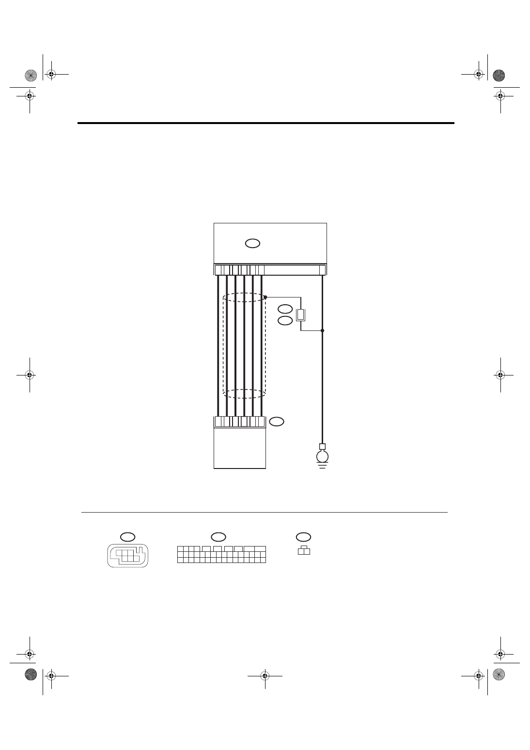
WIRING DIAGRAM:
VDC00222
28
2
1
30
3
16
6
B312
B347
4
2
1
3
5
6
B230
1
B230
B310
VDCCM & H/U
1
3
4 5 6
2
B312
1 2
B310
E
1 2 3 4
11 12 13 14
27 28 29 30
15 16 17 18
31 32 33 34
19 20 21 22
35 36 37 38
23 24 25 26
39 40 41 42
5
6
7
8
9
10
YAW RATE &
LATERAL G SENSOR
VDC(diag)-120
VEHICLE DYNAMICS CONTROL (VDC) (DIAGNOSTICS)
Diagnostic Procedure with Diagnostic Trouble Code (DTC)
Step
Check
Yes
No
1
CHECK YAW RATE & LATERAL G SENSOR
INSTALLATION.
Is the yaw rate & lateral G sen-
sor installation bolt tightened to
7.5 N
⋅m (0.76 kgf-m, 5.5 ft-lb)?
Tighten the yaw
rate & lateral G
sensor installation
bolt.
2
CHECK LATERAL G SENSOR OUTPUT.
1) Park the vehicle on a level surface.
2) Select {Current Data Display & Save} in
Subaru Select Monitor.
3) Read the lateral G sensor output displayed
on display screen.
Is the indicated reading on the
monitor display
−1.5 —1.5 m/
s
2
?
Replace the yaw
rate & lateral G
sensor.
3
CHECK LATERAL G SENSOR OUTPUT.
1) Turn the ignition switch to OFF.
2) Remove the yaw rate & lateral G sensor
from vehicle.
3) Turn the ignition switch to ON, and select
{Current Data Display & Save} in Subaru
Select Monitor.
4) Read the lateral G sensor output displayed
on display.
When the yaw rate & lateral G
sensor is inclined 90
° to the
right, is the indicated value 6.8
— 12.8 m/s
2
?
Replace the yaw
rate & lateral G
sensor.
4
CHECK LATERAL G SENSOR.
Read the lateral G sensor output displayed on
display.
When the yaw rate & lateral G
sensor is inclined 90
° to the
left, is the indicated value
−6.8
—
−12.8 m/s
2
?
Replace the yaw
rate & lateral G
sensor.
5
CHECK POOR CONTACT IN CONNECTORS.
Turn the ignition switch to OFF.
Is there poor contact in con-
nector between VDCCM&H/U
and yaw rate & lateral G sen-
sor?
Repair the con-
nector.
6
CHECK VDCCM&H/U.
1) Connect all the connectors.
2) Perform the clear memory mode.
3) Perform the inspection mode.
4) Read the DTC.
Is the same DTC displayed?
Replace the
VDCCM&H/U.
<Ref. to VDC-7,
VDC Control Mod-
ule and Hydraulic
Control Unit
(VDCCM&H/U).>
7
CHECK OTHER DTC DETECTION.
Is any other DTC displayed?
Perform the diag-
nosis according to
DTC.
Temporary poor
contact occurs.
Нет комментариевНе стесняйтесь поделиться с нами вашим ценным мнением.
Текст