Subaru Legacy (2005 year). Service manual — part 880
AC(diag)-37
HVAC SYSTEM (AUTO A/C) (DIAGNOSTICS)
Diagnostic Procedure for Sensors
D: SUNLOAD SENSOR
TROUBLE SYMPTOM:
• Sensor identifies that sunlight is at maximum. Then, A/C system is controlled to COOL side.
• Sensor identifies that sunlight is at minimum. Then, A/C system is controlled to HOT side.
NOTE:
When the sunload sensor check is conducted indoors or in the shade, open circuit might be indicated. Always
check the sunload sensor at the place where the sun shines directly on it.
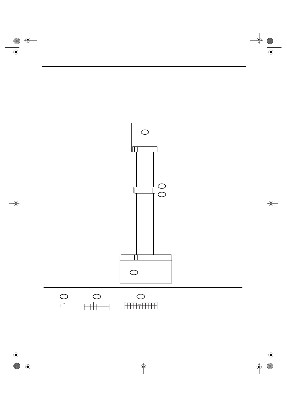
WIRING DIAGRAM:
AC-00832
A: B282
1 2 3 4 5 6 7 8
9 10 11 12 13 14 15 16
i51
A: B282
A8
A6
2
1
i3
B38
i51
1 2
AUTO A/C
CONTROL MODULE
3
2
1 2 3 4
5 6 7 8 9
10 11 12 13 14 15 16 17 18 19 20
B38
SUNLOAD
SENSOR
AC(diag)-38
HVAC SYSTEM (AUTO A/C) (DIAGNOSTICS)
Diagnostic Procedure for Sensors
Step
Check
Yes
No
1
CHECK POWER SUPPLY VOLTAGE FOR
SUNLOAD SENSOR.
1) Turn the ignition switch to OFF.
2) Disconnect the connector from sunload
sensor.
3) Turn the ignition switch to ON.
4) Measure the power supply voltage for sun-
load sensor.
Connector & terminal
(i51) No. 1 (+) — No. 2 (
−
):
Is the voltage approx. 5 V?
2
CHECK HARNESS CONNECTOR BETWEEN
AUTO A/C CONTROL MODULE AND SUN-
LOAD SENSOR.
1) Turn the ignition switch to OFF.
2) Disconnect the connector from auto A/C
control module.
3) Measure the resistance in harness
between auto A/C control module and sunload
sensor.
Connector & terminal
(i51) No. 2 — (B282) No. 6:
Is the resistance less than 1
Ω?
Repair the har-
ness between auto
A/C control mod-
ule and sunload
sensor.
3
CHECK HARNESS CONNECTOR BETWEEN
AUTO A/C CONTROL MODULE AND SUN-
LOAD SENSOR.
Measure the resistance in harness between
auto A/C control module and sunload sensor.
Connector & terminal
(i51) No. 1 — (B282) No. 8:
Is the resistance less than 1
Ω?
Repair the har-
ness between auto
A/C control mod-
ule and sunload
sensor.
4
CHECK INPUT VOLTAGE FOR AUTO A/C
CONTROL MODULE.
1) Connect the connectors of sunload sensor
and auto A/C control module.
2) Turn the ignition switch to ON.
3) Measure the voltage between connector
terminals of auto A/C control module.
Connector & terminal
(B282) No. 8 (+) — (B282) No. 6 (
−
):
Is the voltage approx. 2.5 V?
Replace the sun-
load sensor.
5
CHECK POOR CONTACT.
Check poor contact in auto A/C control module
connector.
Is there poor contact in con-
nector?
Repair the con-
nector.
Replace the auto
A/C control mod-
ule.
AC(diag)-39
HVAC SYSTEM (AUTO A/C) (DIAGNOSTICS)
Diagnostic Procedure for Sensors
E: A/C LOCK SENSOR
• H6 model
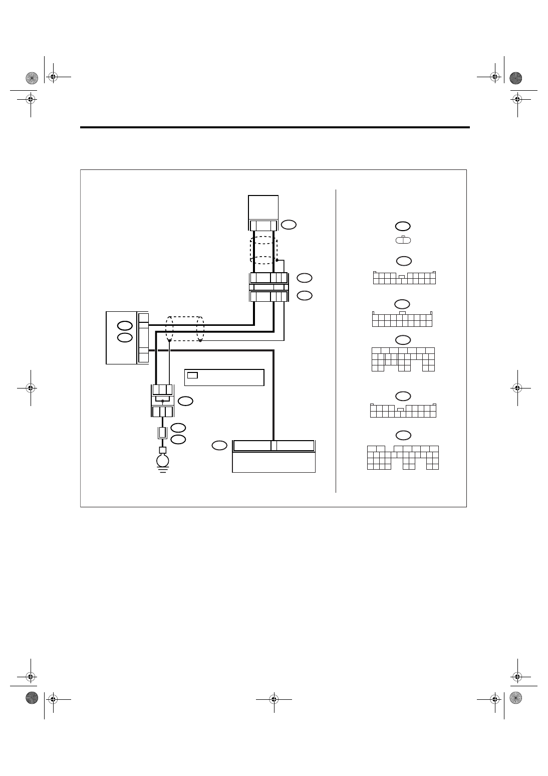
WIRING DIAGRAM:
B283
1 2 3 4
5 6 7 8 9
10 11 12 13 14 15 16 17 18 19 20
F37
A:
5
6
7
8
2
1
9
4
3
10
24
22 23
25
11 12 13 14 15
26 27
28
16 17 18 19
20 21
29 30 31
32 33
34 35
B135
B:
F115
1 2
B137
8
5
6
10 11 12 13 14 15
7
2
1
3
4
16
30
19 20
22
28 29
9
17
18
25
21
23
24
31
26 27
D:
B283
1 2 3 4 5 6 7 8 9 10
11 12 13 14 15 16 17 18 19 20
B143
1 2 3 4
5 6 7 8 9
10 11 12 13 14 15 16 17 18 19 20
B:
E
36
B21
E2
B122
*
*
*
B1
B135
B23
D17
ECM
B137
B:
D:
6
A20
A18
A16
F37
A:
B143
B:
B10
2
1
F115
B12
B14
AC-01703
AUTO A/C CONTROL MODULE
MAIN
FUSE
BOX
(M/B)
A/C
LOCK
SENSOR
JOINT
CONNECTOR
B
*
: TERMINAL No. RANDOM
ARRANGEMENT
AC(diag)-40
HVAC SYSTEM (AUTO A/C) (DIAGNOSTICS)
Diagnostic Procedure for Sensors
Step
Check
Yes
No
1
CHECK A/C LOCK SENSOR SIGNAL.
1) Turn the ignition switch to OFF.
2) Connect the Subaru Select Monitor to data
link connector.
3) Start the engine and turn A/C to ON.
4) Read the data of A/C lock signal using Sub-
aru Select Monitor.
NOTE:
• Subaru Select Monitor
For detailed operation procedure, refer to
“READ CURRENT DATA FOR ENGINE”. <Ref.
to EN(H6DO)(diag)-27, READ CURRENT
DATA FOR ENGINE. (NORMAL MODE),
OPERATION, Subaru Select Monitor.>
Is the A/C lock signal ON?
2
CHECK A/C LOCK SENSOR SIGNAL.
1) Start the engine and turn A/C to ON.
2) Measure the voltage between auto A/C
control module connector and chassis ground.
Connector & terminal
(B283) No. 6 (+) — Chassis ground (
−
):
Is the voltage 7 — 14 V?
Replace the auto
A/C control mod-
ule.
3
CHECK OUTPUT OF ECM.
Measure the voltage between ECM and chas-
sis ground.
Connector & terminal
(D137) No. 17 (+) — Chassis ground (
−
):
Is the voltage 7 — 14 V?
Repair the har-
ness between
ECM and auto A/C
control module.
Replace the ECM.
4
CHECK A/C LOCK SENSOR.
1) Turn the ignition switch to OFF.
2) Disconnect the ECM connector.
3) Measure the resistance between ECM con-
nector and chassis ground.
Connector & terminal
(B135) No. 23 — Chassis ground:
Is the resistance 240 — 290
Ω?
Replace the ECM. Go to step 5.
5
CHECK A/C LOCK SENSOR.
1) Turn the ignition switch to OFF.
2) Disconnect the main fuse box connector.
3) Measure the resistance between main fuse
box terminals.
Connector & terminal
(F37) No. 16 — No. 18:
Is the resistance 240 — 290
Ω?
6
CHECK A/C LOCK SENSOR.
1) Turn the ignition switch to OFF.
2) Disconnect the A/C lock sensor connector.
3) Measure the resistance between A/C lock
sensor terminals.
Connector & terminal
(F115) No. 1 — No. 2:
Is the resistance 240 — 290
Ω?
Repair or replace
the harness
between A/C lock
sensor and main
fuse box.
Replace the A/C
compressor
assembly. (A/C
lock switch is
faulty.)
7
CHECK MAIN FUSE BOX.
1) Turn the ignition switch to OFF.
2) Disconnect the connector, and measure the
resistance between main fuse box terminals.
Connector & terminal
(F37) No. 16 — (F143) No. 12:
(F37) No. 18 — (F143) No. 14:
Is the resistance less than 10
Ω?
Repair or replace
the harness
between A/C lock
sensor and main
fuse box.
Replace the main
fuse box.
Нет комментариевНе стесняйтесь поделиться с нами вашим ценным мнением.
Текст