Subaru Legacy (2005 year). Service manual — part 343
EN(H4DOTC)(diag)-141
ENGINE (DIAGNOSTICS)
Diagnostic Procedure with Diagnostic Trouble Code (DTC)
AK:DTC P0365 CAMSHAFT POSITION SENSOR “B” CIRCUIT (BANK 1)
DTC DETECTING CONDITION:
Immediately at fault recognition
TROUBLE SYMPTOM:
• Engine stalls.
• Failure of engine to start
CAUTION:
After repair or replacement of faulty parts, perform Clear Memory Mode <Ref. to EN(H4DOTC)(diag)-
37, OPERATION, Clear Memory Mode.> and Inspection Mode <Ref. to EN(H4DOTC)(diag)-30, PROCE-
DURE, Inspection Mode.>.
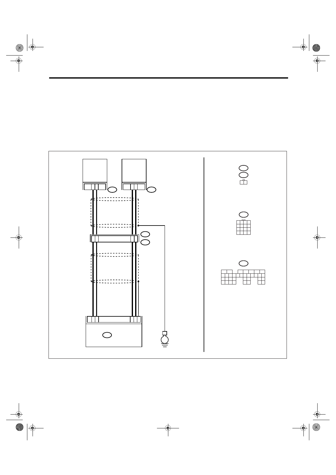
WIRING DIAGRAM:
EN-01956
E1
E65
B20
2
1
11
10
B135
ECM
20
28
21
30
29
E
E65
1 2
B20
EXHAUST
CAMSHAFT
POSITION
SENSOR LH
B135
5
6
7
8
2
1
9
4
3
10
24
22 23
25
11 12 13 14 15
26 27
28
16 17 18 19
20 21
29 30 31
32 33
34 35
E62
2
1
EXHAUST
CAMSHAFT
POSITION
SENSOR RH
12
9
1 2 3 4
5 6 7 8
9 10 11 12
13 14 15 16
E62

EN(H4DOTC)(diag)-142
ENGINE (DIAGNOSTICS)
Diagnostic Procedure with Diagnostic Trouble Code (DTC)
Step
Check
Yes
No
1
CHECK HARNESS BETWEEN CAMSHAFT
POSITION SENSOR AND ECM CONNEC-
TOR.
1) Turn the ignition switch to OFF.
2) Disconnect the connector from camshaft
position sensor.
3) Measure the resistance of harness
between camshaft position sensor connector
and ECM.
Connector & terminal
(E62) No. 1 — (B135) No. 29:
(E62) No. 2 — (B135) No. 21:
Is the resistance less than 1
Ω?
Repair the har-
ness and connec-
tor.
NOTE:
In this case, repair
the following:
• Open circuit of
harness between
camshaft position
sensor and ECM
connector
• Poor contact in
ECM connector
• Poor contact in
coupling connector
2
CHECK HARNESS BETWEEN CAMSHAFT
POSITION SENSOR AND ECM CONNEC-
TOR.
Measure the resistance of harness between
camshaft position sensor connector and
engine ground.
Connector & terminal
(E62) No. 1 — Engine ground:
(E62) No. 2 — Engine ground:
Is the resistance more than 1
M
Ω?
Repair the ground
short circuit of har-
ness between
camshaft position
sensor and ECM
connector.
NOTE:
The harness be-
tween both con-
nectors are
shielded. Repair
the ground short
circuit of harness
with shield.
3
CHECK CONDITION OF CAMSHAFT POSI-
TION SENSOR.
Is the camshaft position sensor
installation bolt tightened
securely?
Tighten the cam-
shaft position sen-
sor installation bolt
securely.
4
CHECK CAMSHAFT POSITION SENSOR.
1) Remove the camshaft position sensor.
2) Measure the resistance between connector
terminals of camshaft position sensor.
Terminals
No. 1 — No. 2:
Is the resistance 1 — 4 k
Ω?
Repair the poor
contact in cam-
shaft position sen-
sor connector.
Replace the cam-
shaft position sen-
sor. <Ref. to
FU(H4DOTC)-24,
Camshaft Position
Sensor.>

EN(H4DOTC)(diag)-143
ENGINE (DIAGNOSTICS)
Diagnostic Procedure with Diagnostic Trouble Code (DTC)
AL:DTC P0390 CAMSHAFT POSITION SENSOR “B” CIRCUIT (BANK 2)
DTC DETECTING CONDITION:
Immediately at fault recognition
TROUBLE SYMPTOM:
• Engine stalls.
• Failure of engine to start
CAUTION:
After repair or replacement of faulty parts, perform Clear Memory Mode <Ref. to EN(H4DOTC)(diag)-
37, OPERATION, Clear Memory Mode.> and Inspection Mode <Ref. to EN(H4DOTC)(diag)-30, PROCE-
DURE, Inspection Mode.>.
WIRING DIAGRAM:
EN-01956
E1
E65
B20
2
1
11
10
B135
ECM
20
28
21
30
29
E
E65
1 2
B20
EXHAUST
CAMSHAFT
POSITION
SENSOR LH
B135
5
6
7
8
2
1
9
4
3
10
24
22 23
25
11 12 13 14 15
26 27
28
16 17 18 19
20 21
29 30 31
32 33
34 35
E62
2
1
EXHAUST
CAMSHAFT
POSITION
SENSOR RH
12
9
1 2 3 4
5 6 7 8
9 10 11 12
13 14 15 16
E62

EN(H4DOTC)(diag)-144
ENGINE (DIAGNOSTICS)
Diagnostic Procedure with Diagnostic Trouble Code (DTC)
Step
Check
Yes
No
1
CHECK HARNESS BETWEEN CAMSHAFT
POSITION SENSOR AND ECM CONNEC-
TOR.
1) Turn the ignition switch to OFF.
2) Disconnect the connector from camshaft
position sensor.
3) Measure the resistance of harness
between camshaft position sensor connector
and ECM.
Connector & terminal
(E65) No. 1 — (B135) No. 28:
(E65) No. 2 — (B135) No. 20:
Is the resistance less than 1
Ω?
Repair the har-
ness and connec-
tor.
NOTE:
In this case, repair
the following:
• Open circuit of
harness between
camshaft position
sensor and ECM
connector
• Poor contact in
ECM connector
• Poor contact in
coupling connector
2
CHECK HARNESS BETWEEN CAMSHAFT
POSITION SENSOR AND ECM CONNEC-
TOR.
Measure the resistance of harness between
camshaft position sensor connector and
engine ground.
Connector & terminal
(E65) No. 1 — Engine ground:
(E65) No. 2 — Engine ground:
Is the resistance more than 1
M
Ω?
Repair the ground
short circuit of har-
ness between
camshaft position
sensor and ECM
connector.
NOTE:
The harness be-
tween both con-
nectors are
shielded. Repair
the ground short
circuit of harness
with shield.
3
CHECK CONDITION OF CAMSHAFT POSI-
TION SENSOR.
Is the camshaft position sensor
installation bolt tightened
securely?
Tighten the cam-
shaft position sen-
sor installation bolt
securely.
4
CHECK CAMSHAFT POSITION SENSOR.
1) Remove the camshaft position sensor.
2) Measure the resistance between connector
terminals of camshaft position sensor.
Terminals
No. 1 — No. 2:
Is the resistance 1 — 4 k
Ω?
Repair the poor
contact in cam-
shaft position sen-
sor connector.
Replace the cam-
shaft position sen-
sor. <Ref. to
FU(H4DOTC)-24,
Camshaft Position
Sensor.>
Нет комментариевНе стесняйтесь поделиться с нами вашим ценным мнением.
Текст