Subaru Legacy (2005 year). Service manual — part 614
5AT(diag)-47
AUTOMATIC TRANSMISSION (DIAGNOSTICS)
Diagnostic Procedure with Diagnostic Trouble Code (DTC)
7
CHECK HARNESS ASSEMBLY.
1) Turn the ignition switch to OFF.
2) Disconnect the connector from transmis-
sion.
3) Disconnect the connector from turbine
speed sensor 1.
4) Measure the resistance between transmis-
sion connector and turbine speed sensor 1
connector.
Connector & terminal
(T4) No. 7 — (AT1) No. 3:
(T3) No. 7 — (AT1) No. 2:
(AT1) No. 1 — Chassis ground:
Is the resistance less than 1
Ω?
Repair the open
circuit of harness
between TCM and
transmission con-
nector, and poor
contact in connec-
tor.
8
CHECK HARNESS ASSEMBLY.
Measure the resistance between transmission
connector and chassis ground.
Connector & terminal
(T4) No. 7 — Chassis ground:
(T3) No. 7 — Chassis ground:
Is the resistance more than 1
M
Ω?
Repair the short
circuit of harness
between TCM and
transmission con-
nector.
9
CHECK INPUT SIGNAL FOR TCM USING
SUBARU SELECT MONITOR.
1) Connect all the connectors.
2) Jack-up the vehicle and support with rigid
racks.
NOTE:
Raise all wheels off floor.
3) Start the engine, and set the vehicle in 4th
speed driving condition of manual mode.
NOTE:
Turbine speed sensor 1 signal can be mea-
sured only on 4th speed.
4) Read the current data of torque converter
turbine speed sensor and turbine speed sen-
sor 1 using Subaru Select Monitor. <Ref. to
5AT(diag)-17, READ CURRENT DATA, OPER-
ATION, Subaru Select Monitor.>
NOTE:
The speed difference between front and rear
wheels may light the ABS warning light, but this
indicates no malfunction. When AT control di-
agnosis is finished, perform the ABS memory
clearance procedure of on-board diagnostics
system. <Ref. to ABS(diag)-26, Clear Memory
Mode.>
Does the value of the turbine
speed sensor 1 change
depending on the acceleration
and deceleration of the vehi-
cle? Also, does the value of
torque converter turbine speed
sensor almost correspond with
the value of turbine speed sen-
sor 1?
Even if the SPORT
indicator lights
blinks, the system
is in normal condi-
tion. A temporary
poor contact of
connector or har-
ness may be the
cause. Repair the
poor contact of
harness between
ATF temperature
sensor and trans-
mission connector.
Replace the tur-
bine speed sensor
1. <Ref. to 5AT-57,
Turbine Speed
Sensor 1.>
Step
Check
Yes
No
5AT(diag)-48
AUTOMATIC TRANSMISSION (DIAGNOSTICS)
Diagnostic Procedure with Diagnostic Trouble Code (DTC)
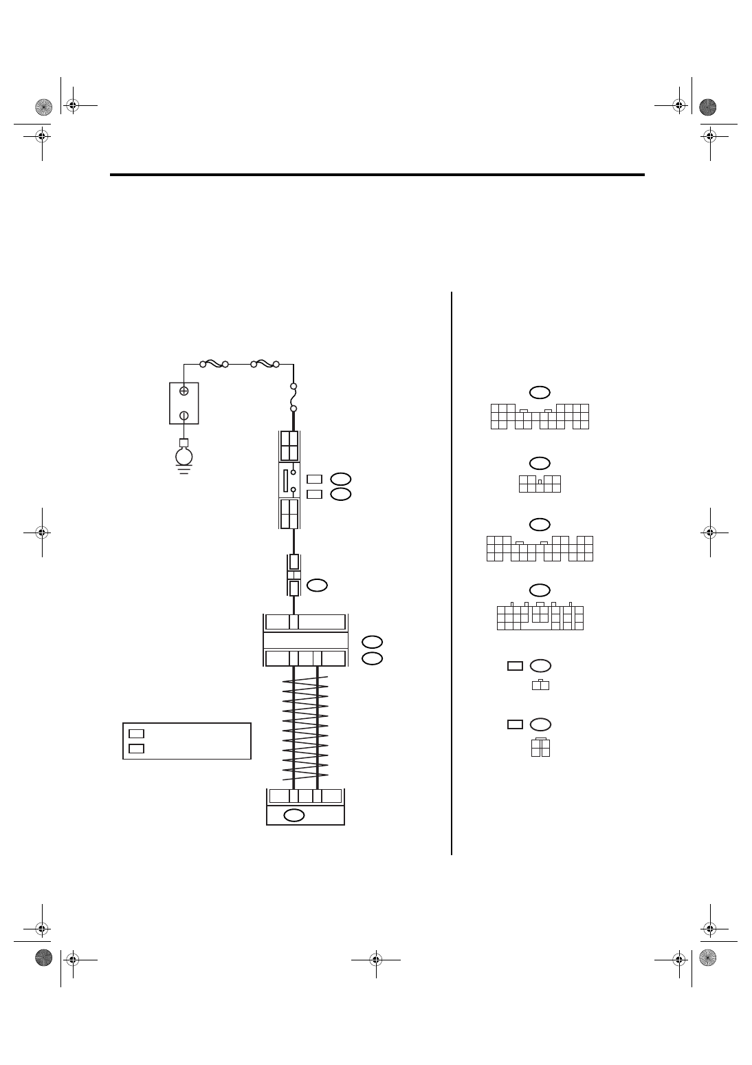
E: DTC P0719 TORQUE CONVERTER/BRAKE SWITCH “B” CIRCUIT LOW
DTC DETECTING CONDITION:
Brake switch malfunction, open input signal circuit
TROUBLE SYMPTOM:
• Brake down control is not operated at SPORT mode.
• No lock-up occurs at braking.
WIRING DIAGRAM:
AT-03175
B159
B280
B:
B281
C:
C23
B20
B30
B159
2
1
3 4
8 9
7
6
5
B280
8
7
6
5
4
3
2
1
22
23
21
20
19
16
15
14
13
12
11
10
9
17
30
18
29
28
27
26
25
24
B281
8
7
6
5
4
3
2
1
21
22
20
19
16
15
14
13
12
11
10
9
17 18
28
27
26
25
24
23
B54
4
3
TCM
B54
FUSE & RELAY
BOX (F/B)
BODY INTEGRATED
MODULE
C:
B:
1 2
7
8
9
5 6
3 4
10 11 12
19 20 21
13
14 15
16
17
18
22
23
24
MAIN SBF
SBF-2
No.8
E
B
A
TTER
Y
B65
1 2
B64
1
2
3
4
WC
OC :
:
B65
WC
B64
OC :
:
STOP LIGHT
SWITCH
32
WC
WC
12
OC
OC
5
9
OC
WC : WITH CRUISE CONTROL
: WITHOUT CRUISE CONTROL
5AT(diag)-49
AUTOMATIC TRANSMISSION (DIAGNOSTICS)
Diagnostic Procedure with Diagnostic Trouble Code (DTC)
Step
Check
Yes
No
1
CHECK DTC.
Is any of following DTC dis-
played? / AT CAN Communica-
tion Circuit / Output Speed
Sensor Circuit / AT Vehicle
Speed Sensor Circuit Malfunc-
tion (Rear Wheel)
Perform the diag-
nosis according to
DTC.
2
CHECK BODY INTEGRATED MODULE.
1) Turn the ignition switch to OFF.
2) Connect the Subaru Select Monitor to data
link connector.
3) Turn the ignition switch to ON. (engine
OFF)
4) Turn the Subaru Select Monitor power
switch to ON.
5) Depress the brake pedal.
6) Read the data of brake pedal switch using
Subaru Select Monitor. <Ref. to LAN(diag)-14,
OPERATION, Subaru Select Monitor.>
Is ON displayed?
3
CHECK TCM.
Read the data of brake pedal switch using
Subaru Select Monitor. <Ref. to 5AT(diag)-17,
OPERATION, Subaru Select Monitor.>
Is ON displayed?
A temporary poor
contact of connec-
tor or harness may
be the cause.
Check the poor
contact.
Replace the TCM.
<Ref. to 5AT-61,
Transmission Con-
trol Module
(TCM).>
4
CHECK BODY INTEGRATED MODULE IN-
PUT SIGNAL.
1) Disconnect the connector from body inte-
grated module.
2) Depress the brake pedal.
3) Measure the voltage between body inte-
grated module connector and chassis ground.
Connector & terminal
(B281) No. 23 (+) — Chassis ground (
−
):
Is the voltage more than 10 V? Go to step 7.
5
CHECK HARNESS CONNECTOR BETWEEN
BODY INTEGRATED MODULE AND STOP
LIGHT SWITCH.
1) Turn the ignition switch to OFF.
2) Disconnect the connector from stop light
switch.
3) Measure the resistance of harness
between body integrated module and stop light
switch.
Connector & terminal
With cruise control
(B281) No. 23 — (B65) No. 3:
Without cruise control
(B281) No. 23 — (B64) No. 2:
Is the resistance less than 1
Ω?
Repair the open
circuit of harness
between body inte-
grated module and
stop light switch.
6
CHECK HARNESS CONNECTOR BETWEEN
BODY INTEGRATED MODULE AND STOP
LIGHT SWITCH.
Measure the resistance of harness between
body integrated module connector and stop
light switch.
Connector & terminal
(B281) No. 23 — Chassis ground:
Is the resistance more than 1
M
Ω?
Repair the short
circuit of harness
between body inte-
grated module and
stop light switch.
7
CHECK POOR CONTACT.
Is there poor contact in input
signal of brake switch?
Repair the poor
contact.
Check the body
integrated module.
5AT(diag)-50
AUTOMATIC TRANSMISSION (DIAGNOSTICS)
Diagnostic Procedure with Diagnostic Trouble Code (DTC)
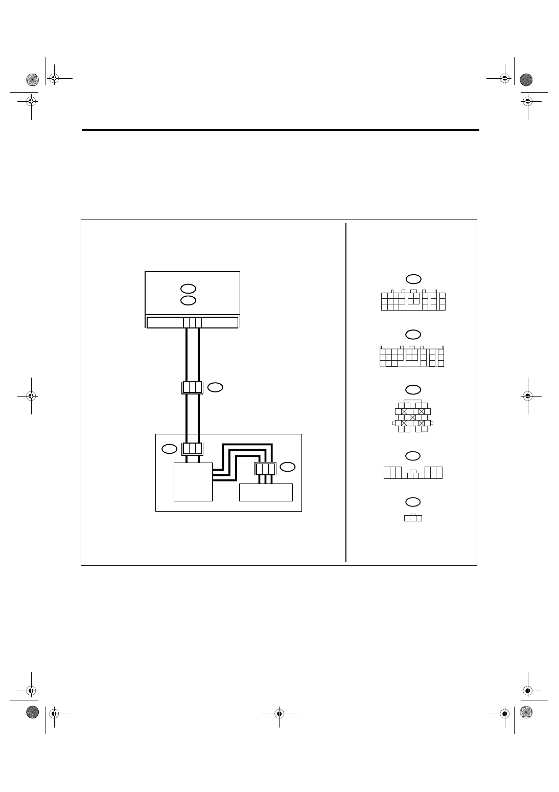
F: DTC P0720 OUTPUT SPEED SENSOR CIRCUIT
DTC DETECTING CONDITION:
• AT vehicle speed signal is abnormal.
• The harness connector between TCM and vehicle speed sensor is in short or open.
TROUBLE SYMPTOM:
• Deterioration of shifting quality.
• Poor driving performance.
WIRING DIAGRAM:
AT-03180
T7
3 2 1
TCM
TRANSMISSION
FRONT VEHICLE
SPEED SENSOR
B55
B:
B54
A:
B11
B7
A16
1 2 3 4
10 11 12
19 20 21
13
5 6
14 15
7
8
9
16
17
18
22
23
24
B55
B11
1 2
5
6 7
8
13
14 15
16
9 10
11 12
3 4
17 18
19 20
B54
1 2
7
8
9
5 6
3 4
10 11 12
19 20 21
13
14 15
16
17
18
22
23
24
A:
B:
T10
14
15
1 2 3
6
8 9 10 11 12 13 14
4 5
15 16
T10
7
1
7
3
2
1
CONTROL
VALVE
T7
Нет комментариевНе стесняйтесь поделиться с нами вашим ценным мнением.
Текст