Subaru Legacy (2005 year). Service manual — part 162
FU(H4SO 2.5)-11
FUEL INJECTION (FUEL SYSTEMS)
Throttle Body
2. Throttle Body
A: REMOVAL
1) Disconnect the ground cable from battery.
2) Remove the air intake chamber. <Ref. to
IN(H4SO 2.0)-7, REMOVAL, Air Intake Chamber.>
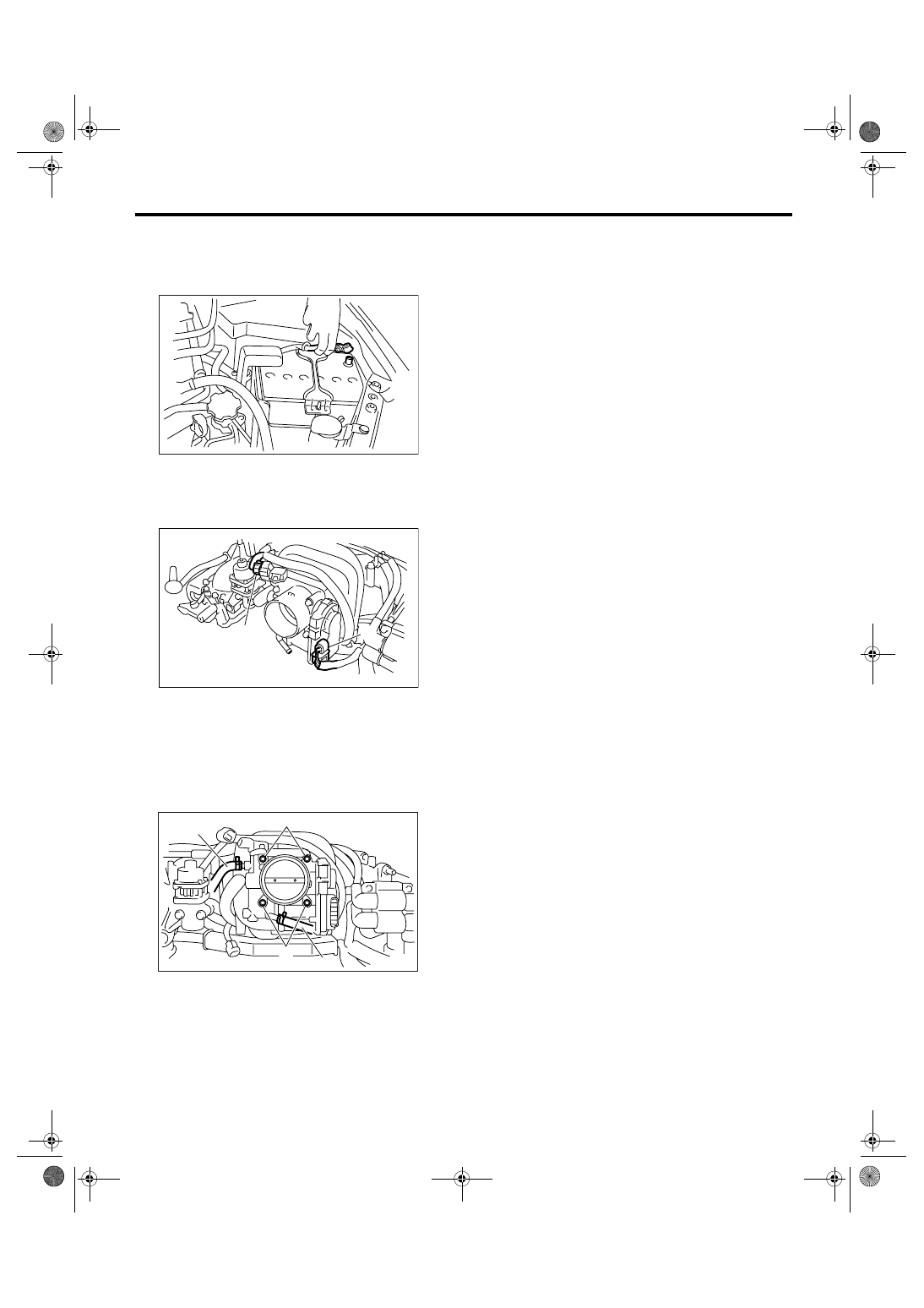
3) Disconnect the connectors from the throttle posi-
tion sensor and manifold absolute pressure sensor.
4) Disconnect the engine coolant hoses (A) from
throttle body.
5) Remove the bolts (B) which secure throttle body
to intake manifold.
B: INSTALLATION
Install in the reverse order of removal.
NOTE:
Use a new gasket.
Tightening torque:
8 N
⋅
m (0.8 kgf-m, 5.9 ft-lb)
(A) Throttle position sensor
(B) Manifold absolute pressure sensor
IN-00203
FU-01083
(B)
(A)
FU-01084
(B)
(A)
(A)
(B)
FU(H4SO 2.5)-12
FUEL INJECTION (FUEL SYSTEMS)
Intake Manifold
3. Intake Manifold
A: REMOVAL
1) Release the fuel pressure. <Ref. to FU(H4SO
2.5)-41, RELEASING OF FUEL PRESSURE,
PROCEDURE, Fuel.>
2) Open the fuel filler flap lid, and remove the fuel
filler cap.
3) Disconnect the ground cable from battery.
4) Remove the air cleaner case and air intake
chamber. <Ref. to IN(H4SO 2.0)-5, REMOVAL, Air
Cleaner Case.> <Ref. to IN(H4SO 2.0)-7, REMOV-
AL, Air Intake Chamber.>
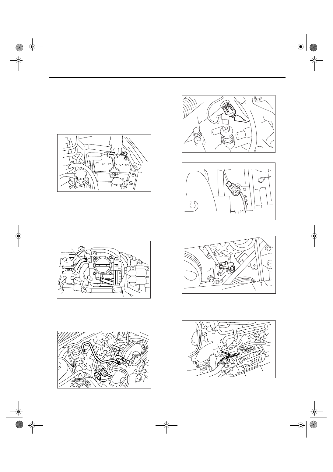
5) Disconnect the spark plug cords from spark
plugs.
6) Disconnect the engine coolant hoses (A) from
throttle body.
7) Disconnect the PCV hose (A) from intake mani-
fold.
8) Disconnect the brake booster hose (B).
9) Disconnect the engine harness connectors (C)
from bulkhead harness connectors.
10) Disconnect the connectors from engine coolant
temperature sensor.
11) Disconnect the knock sensor connector.
12) Disconnect the connector from crankshaft posi-
tion sensor.
13) Disconnect the connector from power steering
pump switch (A).
14) Disconnect the connector from oil pressure
switch (B).
IN-00203
FU-01085
(A)
(A)
FU-01086
(B)
(A)
(C)
FU-00055
FU-01334
FU-00056
FU-01087
(B)
(A)
FU(H4SO 2.5)-13
FUEL INJECTION (FUEL SYSTEMS)
Intake Manifold
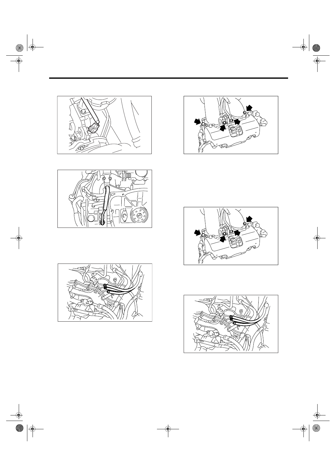
15) Disconnect the connector from camshaft posi-
tion sensor.
16) Remove the EGR pipe from intake manifold.
(EC, EK, K4, EH and ER model)
17) Disconnect the fuel hose from fuel pipe.
WARNING:
• Be careful not to spill fuel.
• Catch the fuel from hoses using a container
or cloth.
18) Remove the bolts which secure intake manifold
to cylinder head.
19) Remove the intake manifold.
B: INSTALLATION
1) Install the intake manifold onto cylinder heads.
NOTE:
Use a new gasket.
Tightening torque:
25 N
⋅
m (2.5 kgf-m, 18 ft-lb)
2) Connect the fuel hoses.
NOTE:
If fuel hoses or clamps are damaged, replace them
with new ones.
Tightening torque:
1.25 N
⋅
m (0.13 kgf-m, 0.94 ft-lb)
(A) Fuel delivery hose
(B) Return hose
(C) Evaporation hose
FU-01335
FU-00148
FU-01088
(A)
(B)
(C)
(A) Fuel delivery hose
(B) Return hose
(C) Evaporation hose
FU-01089
FU-01089
FU-01088
(A)
(B)
(C)
FU(H4SO 2.5)-14
FUEL INJECTION (FUEL SYSTEMS)
Intake Manifold
3) Install the EGR pipe to intake manifold. (EC, EK,
K4, EH and ER model)
Tightening torque:
34 N
⋅
m (3.4 kgf-m, 24.6 ft-lb)
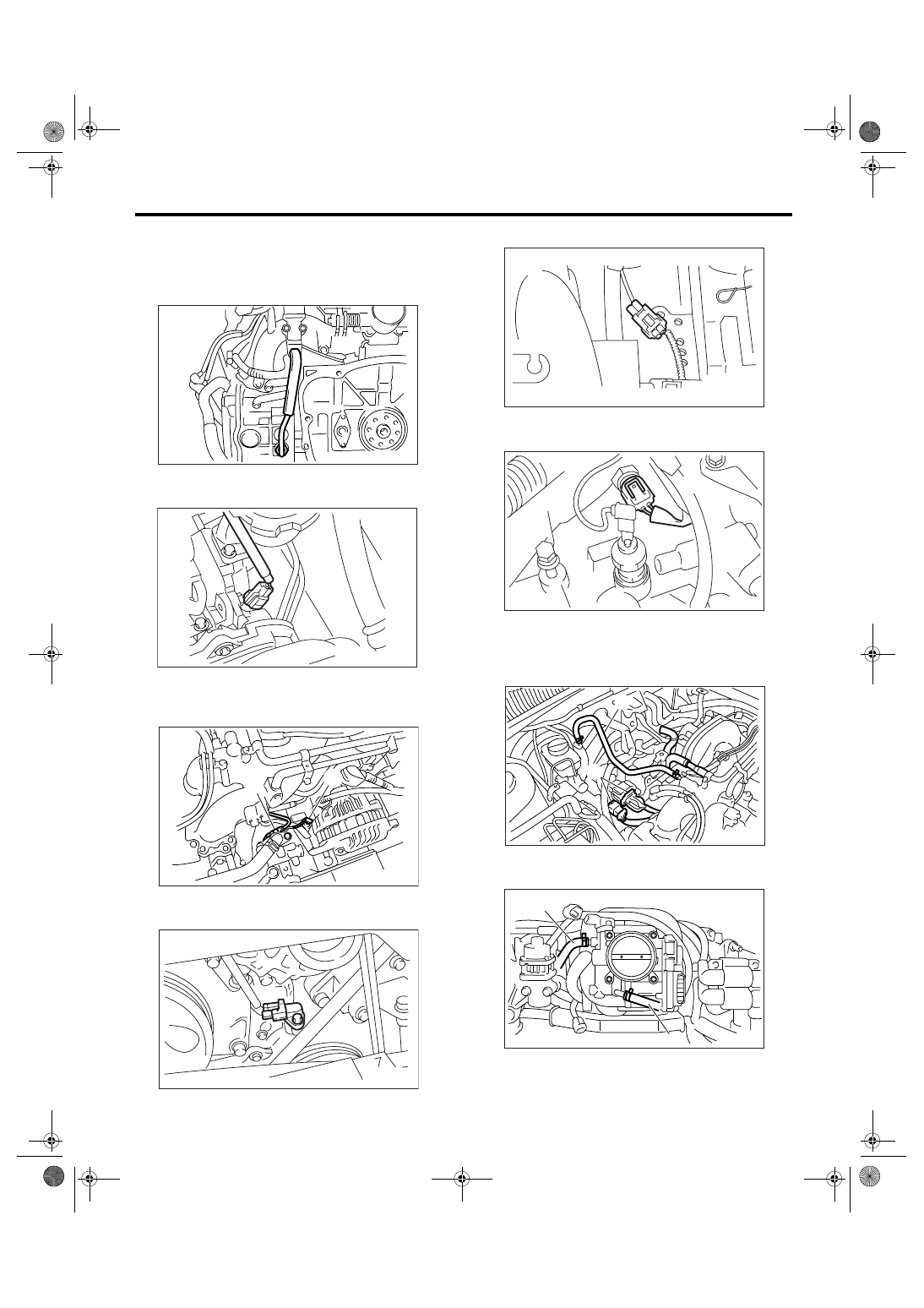
4) Connect the connector to camshaft position sen-
sor.
5) Connect the connector to power steering pump
switch (A).
6) Connect the connector to oil pressure switch (B).
7) Connect the connector to crankshaft position
sensor.
8) Connect the knock sensor connector.
9) Connect the connectors to engine coolant tem-
perature sensor.
10) Connect the PCV hose (A) to intake manifold.
11) Connect the brake booster hose (B).
12) Connect the engine harness connectors (C) to
bulkhead harness connectors.
13) Connect the engine coolant hoses (A) to throt-
tle body.
14) Connect the spark plug cords to spark plugs.
FU-00148
FU-01335
FU-01087
(B)
(A)
FU-00056
FU-01334
FU-00055
FU-01086
(B)
(A)
(C)
FU-01085
(A)
(A)
Нет комментариевНе стесняйтесь поделиться с нами вашим ценным мнением.
Текст