Subaru Legacy (2005 year). Service manual — part 393
ME(H6DO)-47
MECHANICAL
Timing Chain Assembly
15.Timing Chain Assembly
A: REMOVAL
1) Remove the crank pulley. <Ref. to ME(H6DO)-
44, REMOVAL, Crank Pulley.>
2) Remove the front chain cover. <Ref. to
ME(H6DO)-45, REMOVAL, Front Chain Cover.>
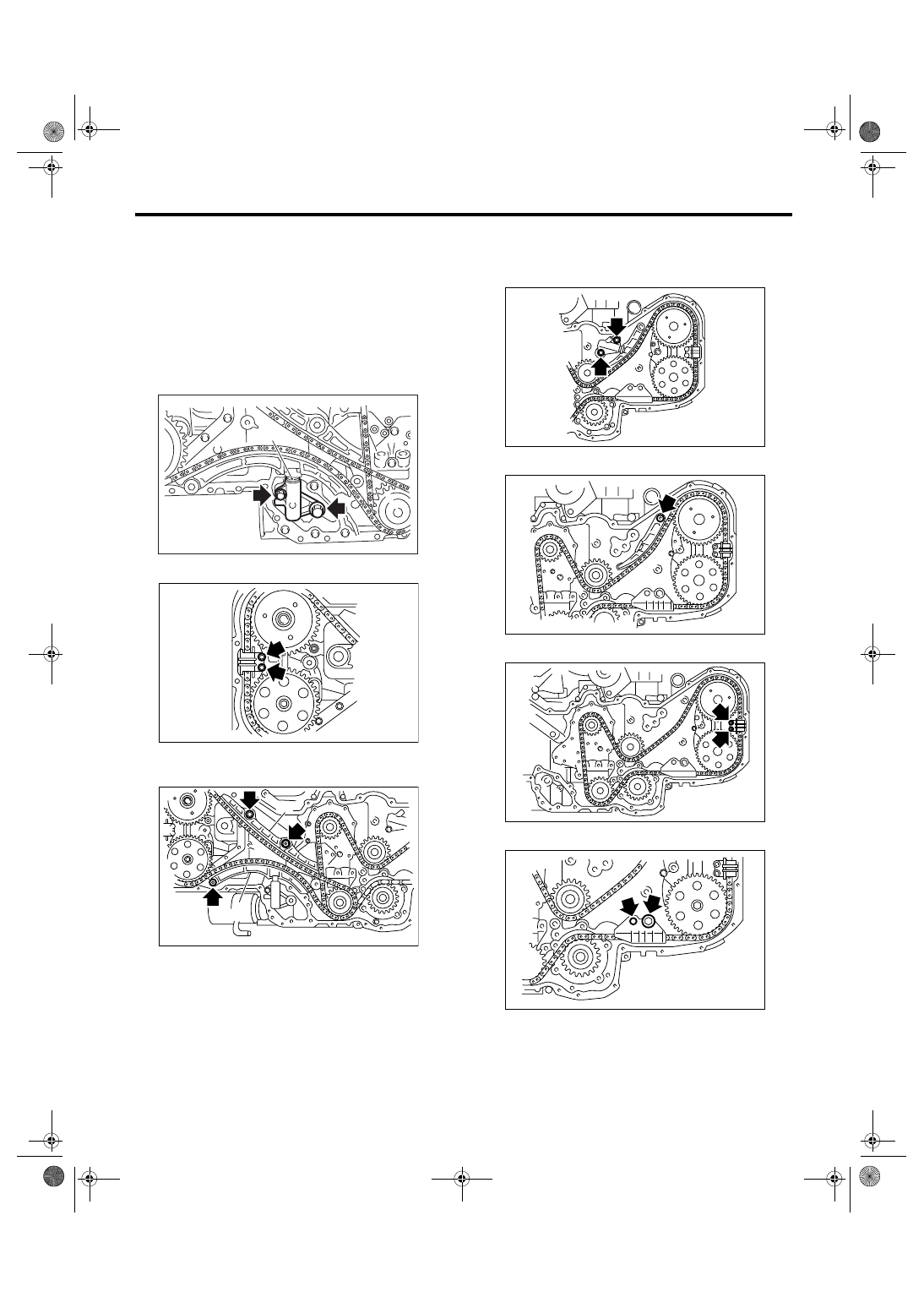
3) Remove the chain tensioner (RH).
NOTE:
Be careful not to come out the plunger (A).
4) Remove the chain guide (RH: between cams).
5) Remove the chain guide (RH).
6) Remove the chain tensioner lever (RH).
7) Remove the timing chain (RH).
8) Remove the chain tensioner (LH).
NOTE:
Be careful not to come out the plunger.
9) Remove the chain tensioner lever (LH).
10) Remove the chain guide (LH: between cams).
11) Remove the chain guide (LH).
(A) Chain guide (RH)
(B) Chain tensioner lever (RH)
(A)
ME-00501
ME-02032
ME-02033
(A)
(B)
ME-02034
ME-02035
ME-02036
ME-02037
ME(H6DO)-48
MECHANICAL
Timing Chain Assembly
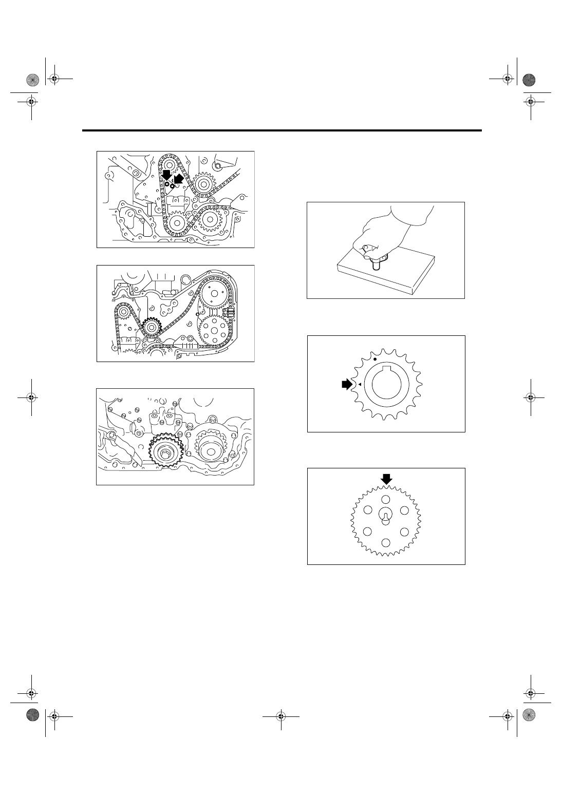
12) Remove the chain guide (center).
13) Remove the idler sprocket (upper).
14) Remove the timing chain (LH).
15) Remove the idler sprocket (lower).
B: INSTALLATION
NOTE:
• Be careful that the foreign matter is not into or
onto assembled component during installation.
• Apply engine oil to the chain guide, chain ten-
sioner lever and idler sprocket when installing.
1) Preparation for chain tensioner installation
(1) Insert the screw, spring pin and tension rod
into tensioner body.
(2) While depressing the tensioner onto rubber
mat, twist it to shorten tension rod. Then insert
the thin pin into the hole between tension rod
and tension body to keep shortened.
NOTE:
Work on the rubber mat or other anti-skid materials.
2) Using the ST, align the “Top mark” on crank
sprocket to 9 o’clock position as shown in the figure
ST
18252AA000
CRANKSHAFT SOCKET
3) Using the ST, align the key groove on exhaust
cam sprocket to 12 o’clock position as shown in the
figure
ME-02038
ME-02039
ME-00510
ME-00511
ME-02040
ME-02041
ME(H6DO)-49
MECHANICAL
Timing Chain Assembly
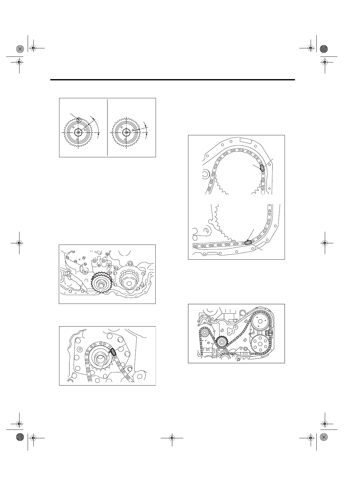
4) Align the intake cam sprocket as shown in the
figure.
5) Turn the crank sprocket clockwise, align the
“Top mark” to 12 o’clock position. (Piston #1 is in
TDC position)
NOTE:
Do not rotate the crank shaft and cam sprocket be-
fore completing timing chain installation.
6) Install the idler sprocket (lower).
Tightening torque:
69 N
⋅
m (7.0 kgf-m, 50.6 ft-lb)
7) Install the timing chain (LH).
(1) Align the timing mark (B) on the crank
sprocket with mark (A) on the timing chain (LH).
(2) Install the timing chain (LH) to the idler
sprocket (lower), water pump, exhaust cam
sprocket (LH) and intake cam sprocket (LH) in
this order.
NOTE:
Check that the mark on timing chain (A) and cam
sprocket (B) is aligned as same as aligned on crank
sprocket.
(3) Install the idler sprocket (upper).
Tightening torque:
69 N
⋅
m (7.0 kgf-m, 50.6 ft-lb)
(A) Top mark
(B) 40
°
(C) 15
°
(A) Gold
(B) Mark
(B)
(A)
LH
RH
(C)
ME-02456
ME-00510
(A)
(B)
ME-00515
(A) Blue
(B) Mark
(A)
(B)
(A)
(B)
ME-02043
ME-02039
ME(H6DO)-50
MECHANICAL
Timing Chain Assembly
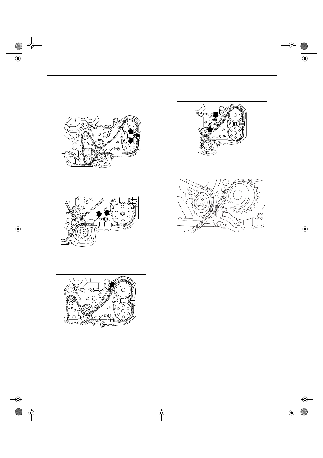
(4) Install the chain guide (LH: between cams).
Tightening torque:
6.4 N
⋅
m (0.65 kgf-m, 4.7 ft-lb)
NOTE:
Use a new installing bolt.
(5) Install the chain guide (LH).
Tightening torque:
16 N
⋅
m (1.6 kgf-m, 11.8 ft-lb)
(6) Install the chain tensioner lever (LH).
Tightening torque:
16 N
⋅
m (1.6 kgf-m, 11.8 ft-lb)
(7) Install the chain tensioner (LH).
Tightening torque:
16 N
⋅
m (1.6 kgf-m, 11.8 ft-lb)
8) Install the timing chain (RH).
(1) Align the marks of timing chain LH and RH
on the idler sprocket (lower).
ME-02036
ME-02037
ME-02035
(A) Idler sprocket (lower)
(B) Timing chain (RH)
(C) Timing chain (LH)
(D) Blue
ME-02034
(A)
(B)
(C)
(D)
ME-00518
Нет комментариевНе стесняйтесь поделиться с нами вашим ценным мнением.
Текст