Subaru Legacy (2005 year). Service manual — part 971
SL-7
SECURITY AND LOCKS
General Description
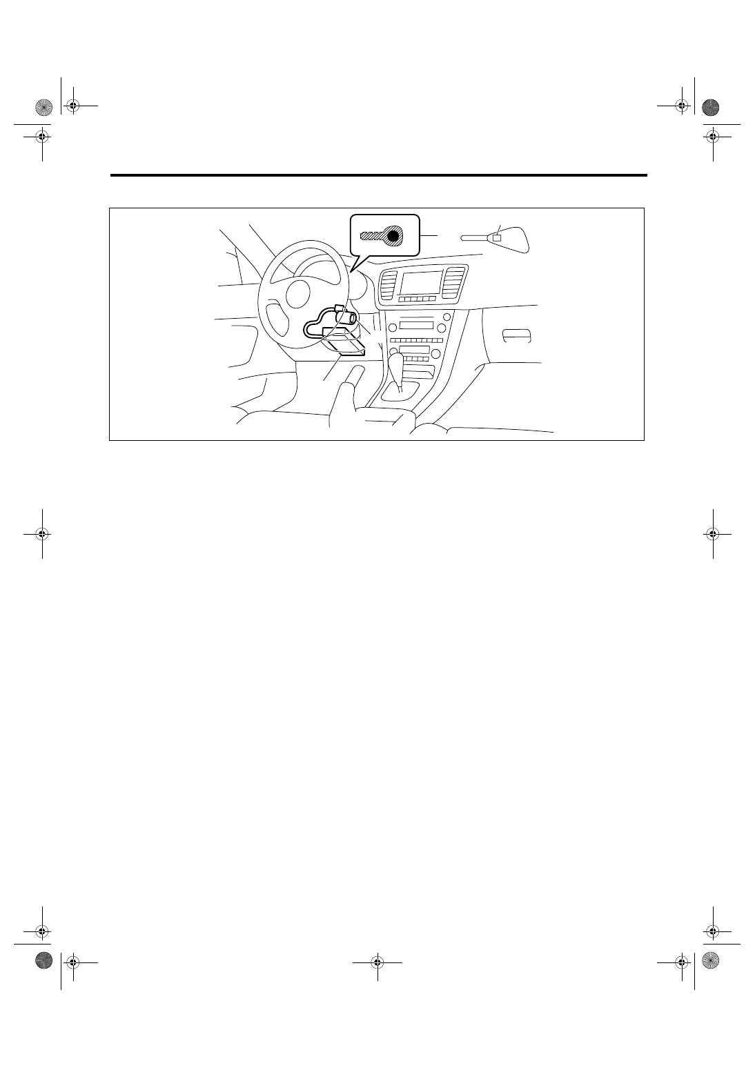
4. IMMOBILIZER SYSTEM
NOTE:
Body integrated module location for RHD model is symmetrically opposite.
(1)
Antenna
(2)
Immobilizer indicator light (LED
bulb)
(3)
Body integrated module
(4)
Transponder
SL-00276
(3)
(2)
(4)
(1)
SL-8
SECURITY AND LOCKS
General Description
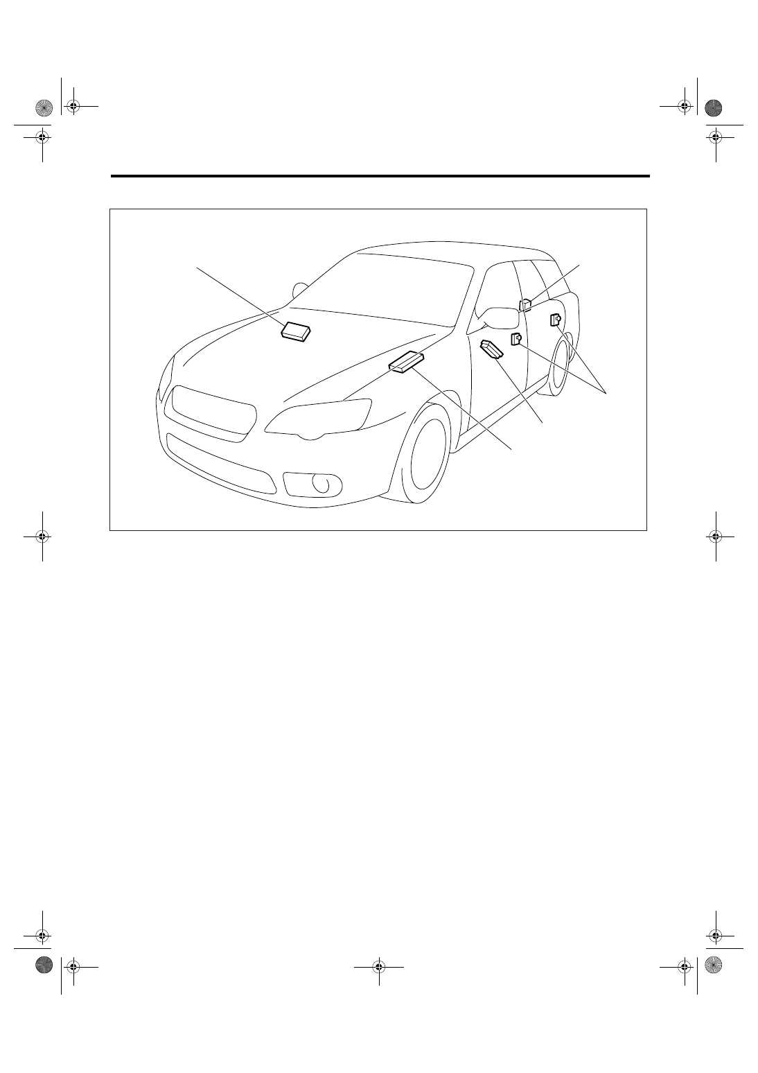
5. KEYLESS ENTRY SYSTEM
B: CAUTION
• Before disassembling or reassembling parts, al-
ways disconnect the battery ground cable. When
repairing the audio, control module, etc. which are
provided with memory functions, record the memo-
ry contents before disconnecting the ground cable
from battery. Otherwise, these contents are erased
upon disconnection.
• Reassemble the parts in the reverse order of dis-
assembly unless otherwise indicated.
• Adjust the parts to the specifications described in
this manual if so designated.
• Connect the connectors securely during reas-
sembly.
• After reassembly, ensure the functional parts op-
erate smoothly.
• The air bag system wiring harness is routed near
electrical parts and switches.
• All air bag system wiring harnesses and connec-
tors are yellow. Do not use the electrical test equip-
ment on these circuits.
• Be careful not to damage the airbag system wir-
ing harness when servicing the ignition key cylin-
der.
(1)
Keyless Entry Control Module
(3)
Door switch
(5)
Power window main switch
(2)
Rear gate latch switch (Wagon)
(4)
Body integrated module
SL-00277
(3)
(2)
(4)
(1)
(5)
SL-9
SECURITY AND LOCKS
General Description
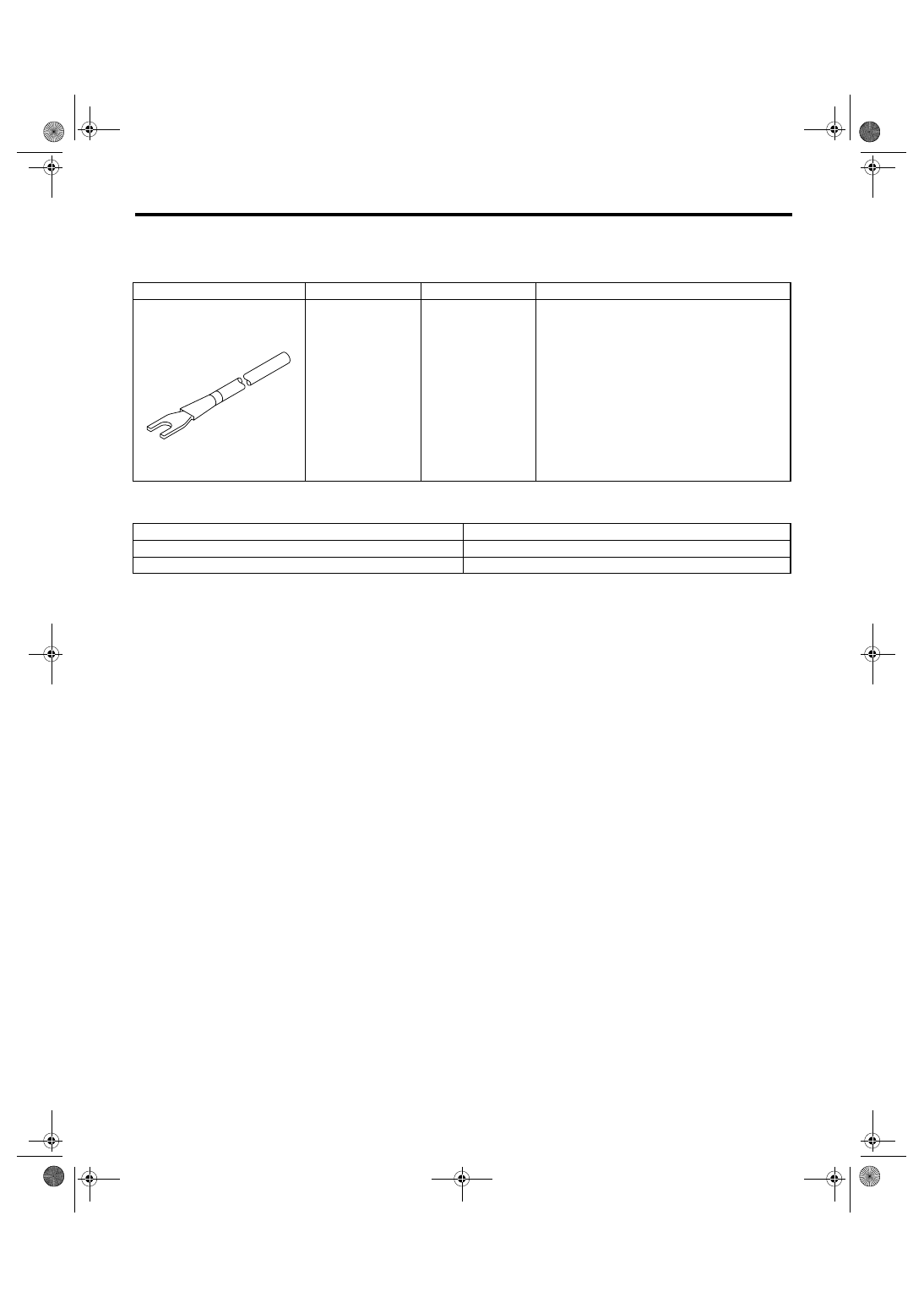
C: PREPARATION TOOL
1. SPECIAL TOOL
2. GENERAL TOOL
ILLUSTRATION
TOOL NUMBER
DESCRIPTION
REMARKS
925580000
PULLER
Used for removing trim clip.
TOOL NAME
REMARKS
Circuit tester
Used for measuring resistance and voltage.
Drill
Used for replacing ignition key lock.
ST-925580000
SL-10
SECURITY AND LOCKS
Door Lock Control System
2. Door Lock Control System
A: WIRING DIAGRAM
1. DOOR LOCK CONTROL
<Ref. to WI-319, WIRING DIAGRAM, Keyless Entry System.>
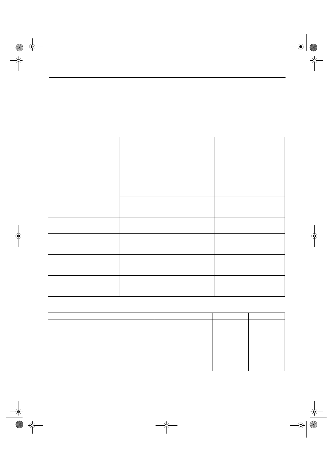
B: INSPECTION
1. SYMPTOM CHART
2. CHECK FUSE
Symptom
Repair order
Reference
The door lock control system does
not operate.
1. Check the fuse.
<Ref. to SL-10, CHECK FUSE,
INSPECTION, Door Lock Control
System.>
2. Check the power supply and ground circuit for
body integrated module.
<Ref. to SL-11, CHECK POWER
SUPPLY AND GROUND CIRCUIT,
INSPECTION, Door Lock Control
System.>
3. Check the door lock switch and circuit.
<Ref. to SL-11, CHECK DOOR
LOCK SWITCH, INSPECTION,
Door Lock Control System.>
4. Check the door lock actuator and circuit.
<Ref. to SL-12, CHECK DOOR
LOCK ACTUATOR AND CIRCUIT,
INSPECTION, Door Lock Control
System.>
The door lock switch does not oper-
ate.
Check the door lock switch.
<Ref. to SL-11, CHECK DOOR
LOCK SWITCH, INSPECTION,
Door Lock Control System.>
A specific door lock actuator does not
operate.
Check the door lock actuator and circuit.
<Ref. to SL-12, CHECK DOOR
LOCK ACTUATOR AND CIRCUIT,
INSPECTION, Door Lock Control
System.>
The key cylinder lock switch does not
operate. (Model with double lock)
Check the key cylinder lock switch and circuit.
The double lock does not operate.
(Model with double lock)
Check the door lock actuator (double lock) and cir-
cuit.
Step
Check
Yes
No
1
CHECK FUSE.
Remove and visually check the fuse No. 3 (in
the fuse and relay box) and No. 7 (in the fuse
and relay box).
Is the fuse blown out?
Replace the fuse
with a new one.
Check the power
supply and ground
circuit. <Ref. to
SL-11, CHECK
POWER SUPPLY
AND GROUND
CIRCUIT,
INSPECTION,
Door Lock Control
System.>
Нет комментариевНе стесняйтесь поделиться с нами вашим ценным мнением.
Текст