Subaru Legacy (2005 year). Service manual — part 449
EN(H6DO)(diag)-109
ENGINE (DIAGNOSTICS)
Diagnostic Procedure with Diagnostic Trouble Code (DTC)
Step
Check
Yes
No
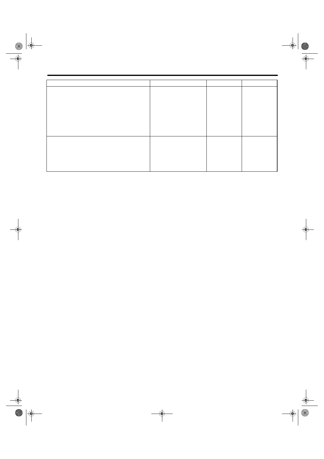
1
CHECK HARNESS BETWEEN ECM AND OIL
SWITCHING SOLENOID VALVE.
1) Turn the ignition switch to OFF.
2) Disconnect the connector from ECM and oil
switching solenoid valve.
3) Measure the resistance between oil switch-
ing solenoid valve and engine ground.
Connector & terminal
(E70) No. 1 — Engine ground:
(E70) No. 2 — Engine ground:
Is the resistance more than 1
M
Ω?
Repair the short
circuit between
ECM and oil
switching solenoid
valve connector.
2
CHECK OIL SWITCHING SOLENOID VALVE.
1) Remove the oil switching solenoid valve
connector.
2) Measure the resistance between oil switch-
ing solenoid valve terminals.
Terminal
No. 1 — No. 2:
Is the resistance 6 — 12
Ω
Repair the poor
contact in ECM
and oil switching
solenoid valve.
Replace the oil
switching solenoid
valve. <Ref. to
ME(H6DO)-80, Oil
Switching Sole-
noid Valve.>
EN(H6DO)(diag)-110
ENGINE (DIAGNOSTICS)
Diagnostic Procedure with Diagnostic Trouble Code (DTC)
S: DTC P0101 MASS OR VOLUME AIR FLOW CIRCUIT RANGE/PERFOR-
MANCE
DTC DETECTING CONDITION:
Detects when malfunction occurs in 2 continuous driving cycles.
TROUBLE SYMPTOM:
• Erroneous idling
• Engine stalls.
• Poor driving performance
CAUTION:
After repair or replacement of faulty parts, conduct Clear Memory Mode <Ref. to EN(H6DO)(diag)-41,
OPERATION, Clear Memory Mode.> and Inspection Mode <Ref. to EN(H6DO)(diag)-34, Inspection
Mode.>.
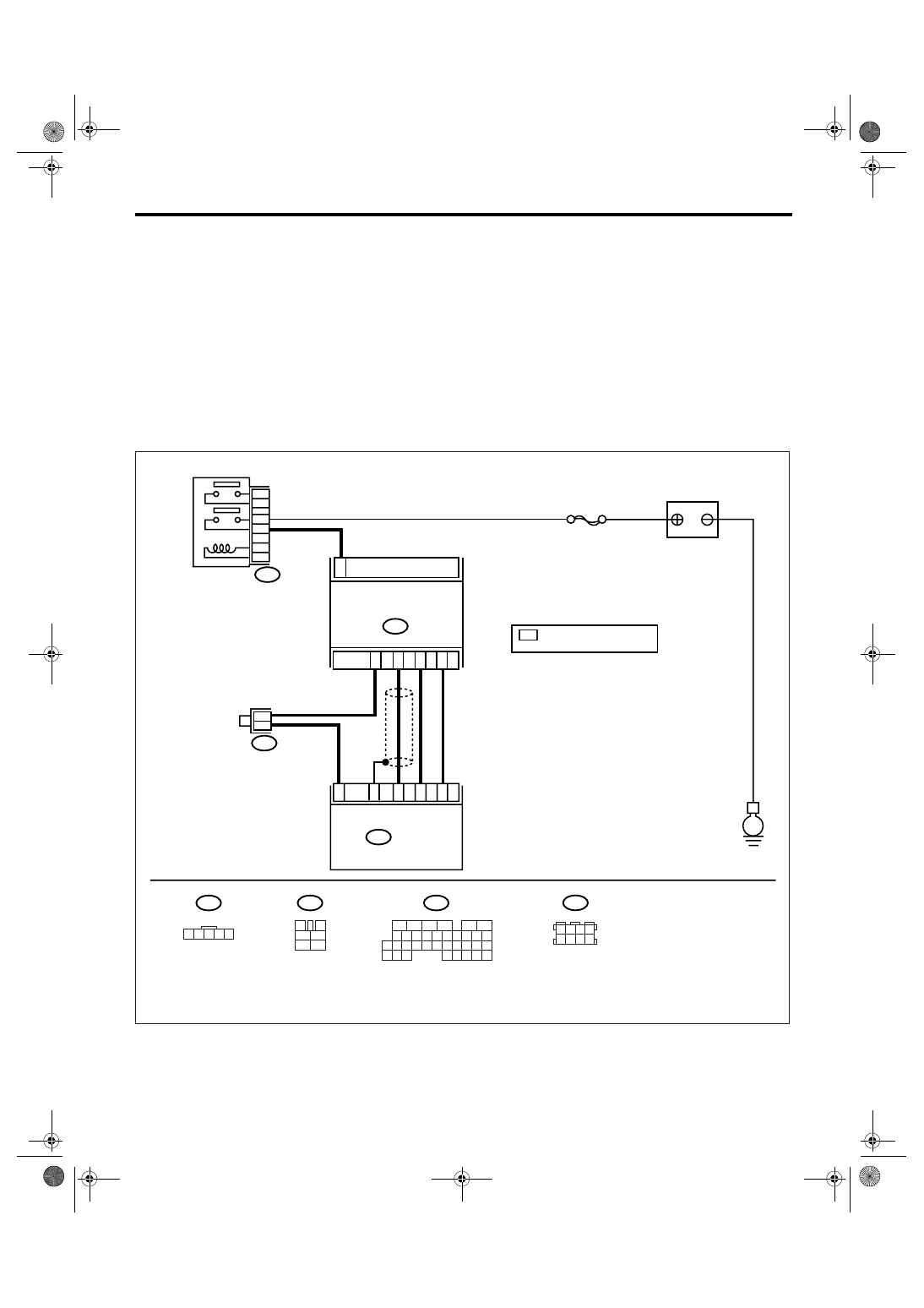
WIRING DIAGRAM:
EN-03496
B83
B3
BATTERY
E
B83
1
B3
MASS AIR FLOW AND INTAKE
AIR TEMPERATURE SENSOR
ECM
B136
SBF-7
1 2 3 4 5
3
4
1
2
5
6
B136
B47
*
*
2
4
3
5
31
13
23
35
32
MAIN RELAY
B47
1 2 3 4
5 6 7 8
5
6
7 8
2
1
9
4
3
10
24
22 23
25
11 12 13 14 15
26 27
28
16
17 18 19 20 21
33 34
29
32
30
31
35
6
4
: TERMINAL No.
RANDOM ARRANGEMENT
*
EN(H6DO)(diag)-111
ENGINE (DIAGNOSTICS)
Diagnostic Procedure with Diagnostic Trouble Code (DTC)
Step
Check
Yes
No
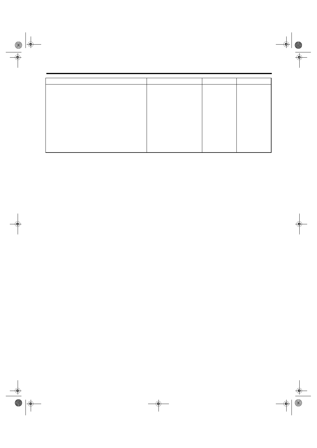
1
CHECK ANY OTHER DTC ON DISPLAY.
Is any other DTC displayed?
Inspect the rele-
vant DTC using
“List of Diagnostic
Trouble Code
(DTC)”. <Ref. to
EN(H6DO)(diag)-
66, List of Diag-
nostic Trouble
Code (DTC).>
NOTE:
In this case, it is
not necessary to
inspect DTC
P0101.
Replace the mass
air flow and intake
air temperature
sensor. <Ref. to
FU(H6DO)-24,
Mass Air Flow and
Intake Air Temper-
ature Sensor.>
EN(H6DO)(diag)-112
ENGINE (DIAGNOSTICS)
Diagnostic Procedure with Diagnostic Trouble Code (DTC)
T: DTC P0102 MASS OR VOLUME AIR FLOW CIRCUIT LOW INPUT
DTC DETECTING CONDITION:
Immediately at fault recognition
TROUBLE SYMPTOM:
• Erroneous idling
• Engine stalls.
• Poor driving performance
CAUTION:
After repair or replacement of faulty parts, conduct Clear Memory Mode <Ref. to EN(H6DO)(diag)-41,
OPERATION, Clear Memory Mode.> and Inspection Mode <Ref. to EN(H6DO)(diag)-34, PROCEDURE,
Inspection Mode.>.
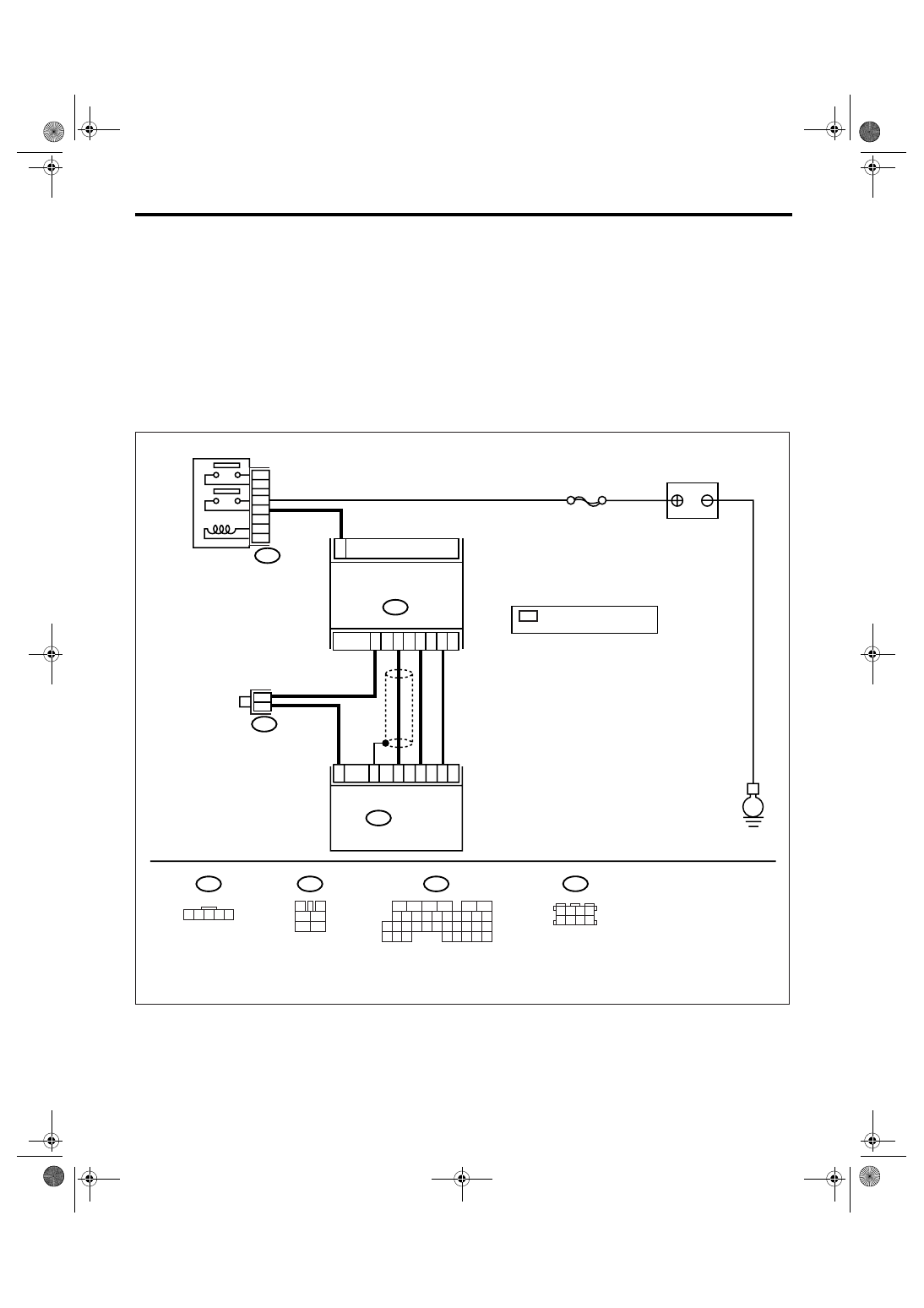
WIRING DIAGRAM:
EN-03496
B83
B3
BATTERY
E
B83
1
B3
MASS AIR FLOW AND INTAKE
AIR TEMPERATURE SENSOR
ECM
B136
SBF-7
1 2 3 4 5
3
4
1
2
5
6
B136
B47
*
*
2
4
3
5
31
13
23
35
32
MAIN RELAY
B47
1 2 3 4
5 6 7 8
5
6
7 8
2
1
9
4
3
10
24
22 23
25
11 12 13 14 15
26 27
28
16
17 18 19 20 21
33 34
29
32
30
31
35
6
4
: TERMINAL No.
RANDOM ARRANGEMENT
*
Нет комментариевНе стесняйтесь поделиться с нами вашим ценным мнением.
Текст