Subaru Legacy (2005 year). Service manual — part 459
EN(H6DO)(diag)-149
ENGINE (DIAGNOSTICS)
Diagnostic Procedure with Diagnostic Trouble Code (DTC)
AJ:DTC P0138 O2 SENSOR CIRCUIT HIGH VOLTAGE (BANK 1 SENSOR 2)
DTC DETECTING CONDITION:
Detects when malfunction occurs in 2 continuous driving cycles.
CAUTION:
After repair or replacement of faulty parts, conduct Clear Memory Mode <Ref. to EN(H6DO)(diag)-41,
OPERATION, Clear Memory Mode.> and Inspection Mode <Ref. to EN(H6DO)(diag)-34, PROCEDURE,
Inspection Mode.>.
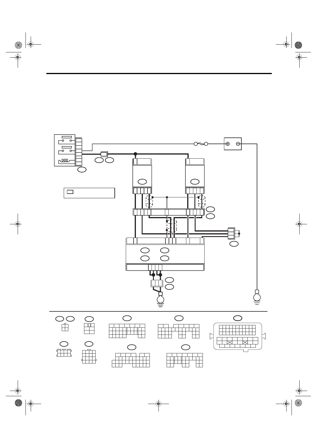
WIRING DIAGRAM:
BATTERY
SBF-5
B47
MAIN RELAY
A4
A5
A6
A7
2
52
54
B21
E2
ECM
B3
D31
D25
D24
B2
C35
4
3
1
REAR
OXYGEN
SENSOR LH
E25
2
4
3
1
REAR
OXYGEN
SENSOR RH
E61
E3
B22
14
13
15
E3
B22
10
11
12
9
B83
B47
3
4
5
6
1
2
EN-03495
B21
1 2 3 4
12 13 14 15
5 6 7 8
16 17 18 19
9 10 11
20 21 22
23 24 25 26 27 28 29 30 31 32 33
35
34
37
36
39
38
41
40
43
42
44
45
47
46
49
48
51
50
53
52
54
B135
5
6
7
8
2
1
9
4
3
10
24
22 23
25
11 12 13 14 15
26 27
28
16 17 18 19
20 21
29 30 31
32 33
34 35
B:
B134
5
6
7
8
2
1
9
4
3
10
24
22 23
25
11 12 13 14 15
26 27
28
16 17
18 19 20 21
33 34
29
32
30 31
A:
16
B134
A:
B135
B:
B136
C:
B137
D:
B22
1 2 3 4
5 6 7 8
9 10 11 12
13 14 15 16
B136
5
6
7 8
2
1
9
4
3
10
24
22 23
25
11 12 13 14 15
26 27
28
16
17 18 19 20 21
33 34
29
32
30
31
35
C:
B137
5
6
7
8
2
1
9
4
3
10
22 23
11 12 13 14 15
24 25
26
16 17
18 19 20 21
27
28 29
30 31
D:
1 2 3 4
5 6 7 8
B83
3 4
1 2
E25
E61
E
E
5
3
: TERMINAL No.
RANDOM ARRANGEMENT
*
*
*
*

EN(H6DO)(diag)-150
ENGINE (DIAGNOSTICS)
Diagnostic Procedure with Diagnostic Trouble Code (DTC)
Step
Check
Yes
No
1
CHECK ANY OTHER DTC ON DISPLAY.
Is any other DTC displayed?
Check DTC using
the List of Diag-
nostic Trouble
Code (DTC). <Ref.
to
EN(H6DO)(diag)-
66, List of Diag-
nostic Trouble
Code (DTC).>
NOTE:
In this case, it is
not necessary to
inspect DTC
P0138.
2
CHECK REAR OXYGEN SENSOR DATA.
1) Warm-up the engine until engine coolant
temperature is above 70
°C (158°F), and lower
the engine speed rapidly from 5,000 rpm.
2) Read the data of rear oxygen sensor signal
using Subaru Select Monitor or general scan
tool.
NOTE:
• Subaru Select Monitor
For detailed operation procedure, refer to
“READ CURRENT DATA FOR ENGINE”. <Ref.
to EN(H6DO)(diag)-26, Subaru Select Moni-
tor.>
• General scan tool
For detailed operation procedure, refer to the
general scan tool operation manual.
Is the voltage more than 250
mV?
3
CHECK HARNESS BETWEEN ECM AND
REAR OXYGEN SENSOR CONNECTOR.
1) Turn the ignition switch to OFF.
2) Disconnect the connector from ECM and
rear oxygen sensor.
3) Measure the resistance of harness
between ECM and rear oxygen sensor con-
nector.
Connector & terminal
(B137) No. 24 — (E61) No. 3:
(B136) No. 35 — (E61) No. 4:
Is the resistance more than 3
Ω?
Repair the open
circuit of harness
between ECM and
rear oxygen sen-
sor connector.
4
CHECK HARNESS BETWEEN REAR OXY-
GEN SENSOR AND ECM CONNECTOR.
1) Turn the ignition switch to OFF.
2) Disconnect the connector from rear oxygen
sensor.
3) Turn the ignition switch to ON.
4) Measure the voltage between rear oxygen
sensor harness connector and chassis ground.
Connector & terminal
(E61) No. 3 (+) — Chassis ground (
−
):
Is the voltage 0.2 — 0.5 V?
Replace the rear
oxygen sensor.
<Ref. to
FU(H6DO)-32,
Rear Oxygen Sen-
sor.>
Repair the har-
ness and connec-
tor.
NOTE:
In this case, repair
the following:
• Open circuit of
harness between
rear oxygen sen-
sor and ECM con-
nector
• Poor contact in
rear oxygen sen-
sor connector
• Poor contact in
ECM connector

EN(H6DO)(diag)-151
ENGINE (DIAGNOSTICS)
Diagnostic Procedure with Diagnostic Trouble Code (DTC)
5
CHECK EXHAUST SYSTEM.
Check exhaust system parts.
NOTE:
Check the following items.
• Loose part and incomplete installation of
exhaust system
• Damage (crack, hole etc.) of parts
• Looseness and ill fitting of parts between
front oxygen (A/F) sensor and rear oxygen
sensor
Is there any fault in exhaust
system?
Repair or replace
faulty parts.
Replace the rear
oxygen sensor.
<Ref. to
FU(H6DO)-32,
Rear Oxygen Sen-
sor.>
Step
Check
Yes
No
EN(H6DO)(diag)-152
ENGINE (DIAGNOSTICS)
Diagnostic Procedure with Diagnostic Trouble Code (DTC)
AK:DTC P0151 O2 SENSOR CIRCUIT LOW VOLTAGE (BANK 2 SENSOR 1)
DTC DETECTING CONDITION:
Immediately at fault recognition
CAUTION:
After repair or replacement of faulty parts, conduct Clear Memory Mode <Ref. to EN(H6DO)(diag)-41,
OPERATION, Clear Memory Mode.> and Inspection Mode <Ref. to EN(H6DO)(diag)-34, PROCEDURE,
Inspection Mode.>.
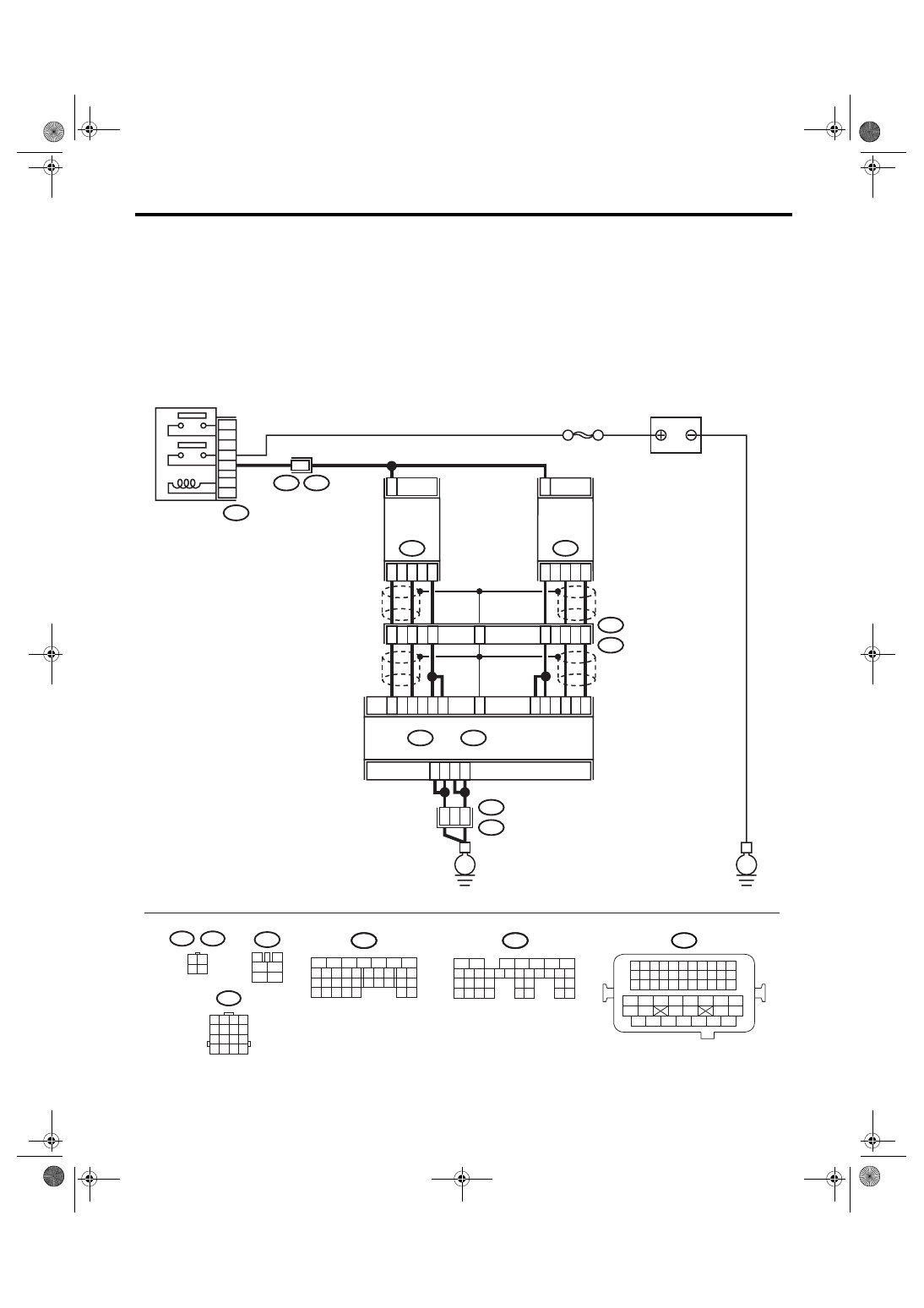
WIRING DIAGRAM:
BATTERY
SBF-5
B47
MAIN RELAY
A4
A5
A6
A7
2
52
54
B21
E2
ECM
A34
A27
B7
A1
A2
A3
A26
A33
4
1
3
FRONT
OXYGEN
(A/F)
SENSOR LH
E24
2
B135
B:
B134
A:
4
3
1
FRONT
OXYGEN
(A/F)
SENSOR RH
E47
E3
B22
8
5
6
E3
B22
2
1
3
4
B47
3
4
5
6
1
2
A25
B22
1 2 3 4
5 6 7 8
9 10 11 12
13 14 15 16
3 4
1 2
E47
E24
B135
5
6
7
8
2
1
9
4
3
10
24
22 23
25
11 12 13 14 15
26 27
28
16 17 18 19
20 21
29 30 31
32 33
34 35
B:
B134
5
6
7
8
2
1
9
4
3
10
24
22 23
25
11 12 13 14 15
26 27
28
16 17
18 19 20 21
33 34
29
32
30 31
A:
B21
1 2 3 4
12 13 14 15
5 6 7 8
16 17 18 19
9 10 11
20 21 22
23 24 25 26 27 28 29 30 31 32 33
35
34
37
36
39
38
41
40
43
42
44
45
47
46
49
48
51
50
53
52
54
E
E
EN-03494
B135
B:
B134
A:
7
5
3
Нет комментариевНе стесняйтесь поделиться с нами вашим ценным мнением.
Текст