Subaru Legacy (2005 year). Service manual — part 409
CO(H6DO)-7
COOLING
General Description
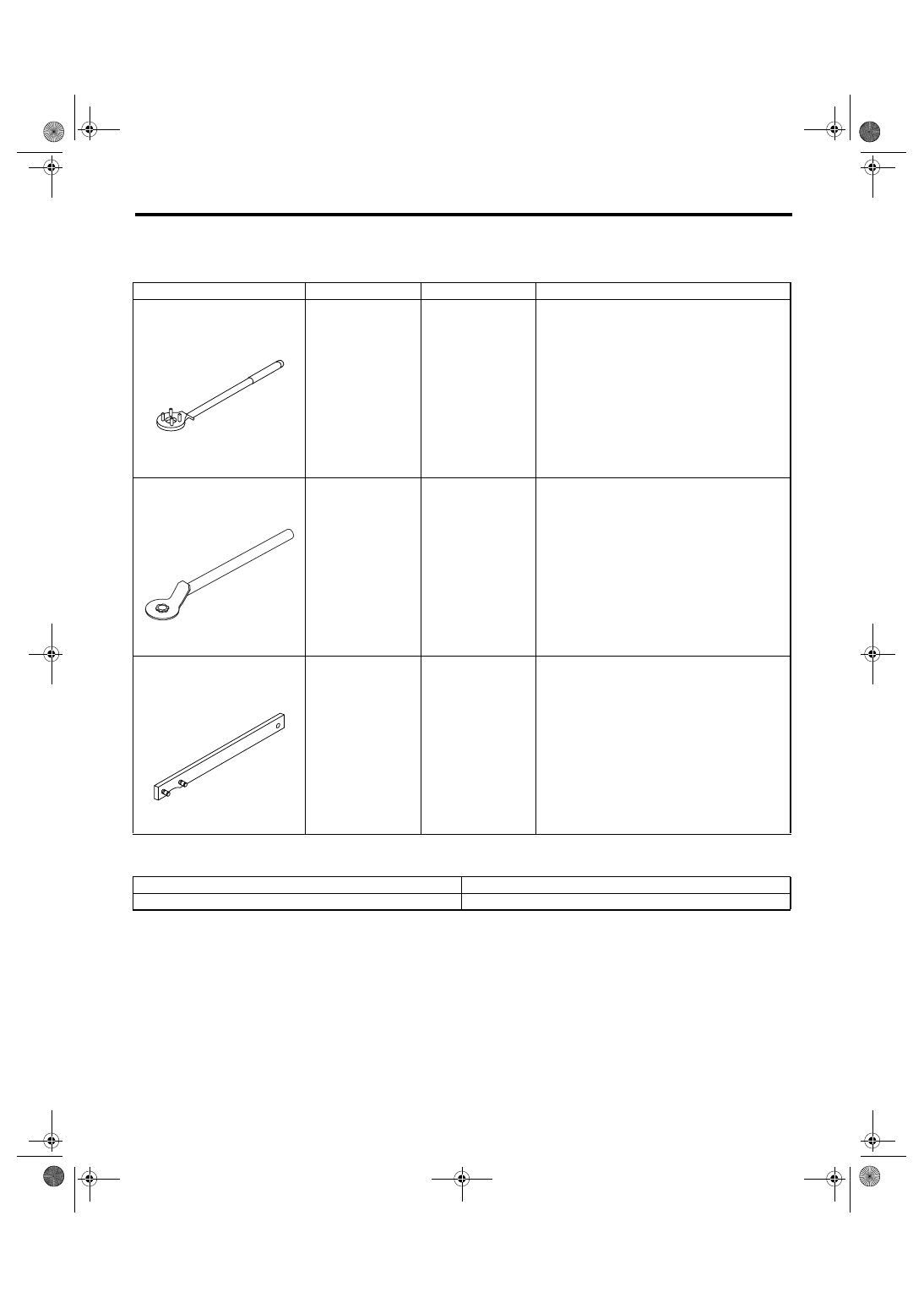
D: PREPARATION TOOL
1. SPECIAL TOOL
2. GENERAL TOOL
ILLUSTRATION
TOOL NUMBER
DESCRIPTION
REMARKS
499977100
CRANK PULLEY
WRENCH
Used for stopping rotation of crank pulley when
loosening and tightening crank pulley bolts.
499977500
CAM SPROCKET
WRENCH
Used for removing and installing intake cam
sprocket.
18231AA020
CAM SPROCKET
WRENCH
Used for removing and installing exhaust cam
sprocket.
TOOL NAME
REMARKS
Radiator cap tester
Used for measuring pressure.
ST-499977100
ST-499977500
ST18231AA020
CO(H6DO)-8
COOLING
Radiator Fan System
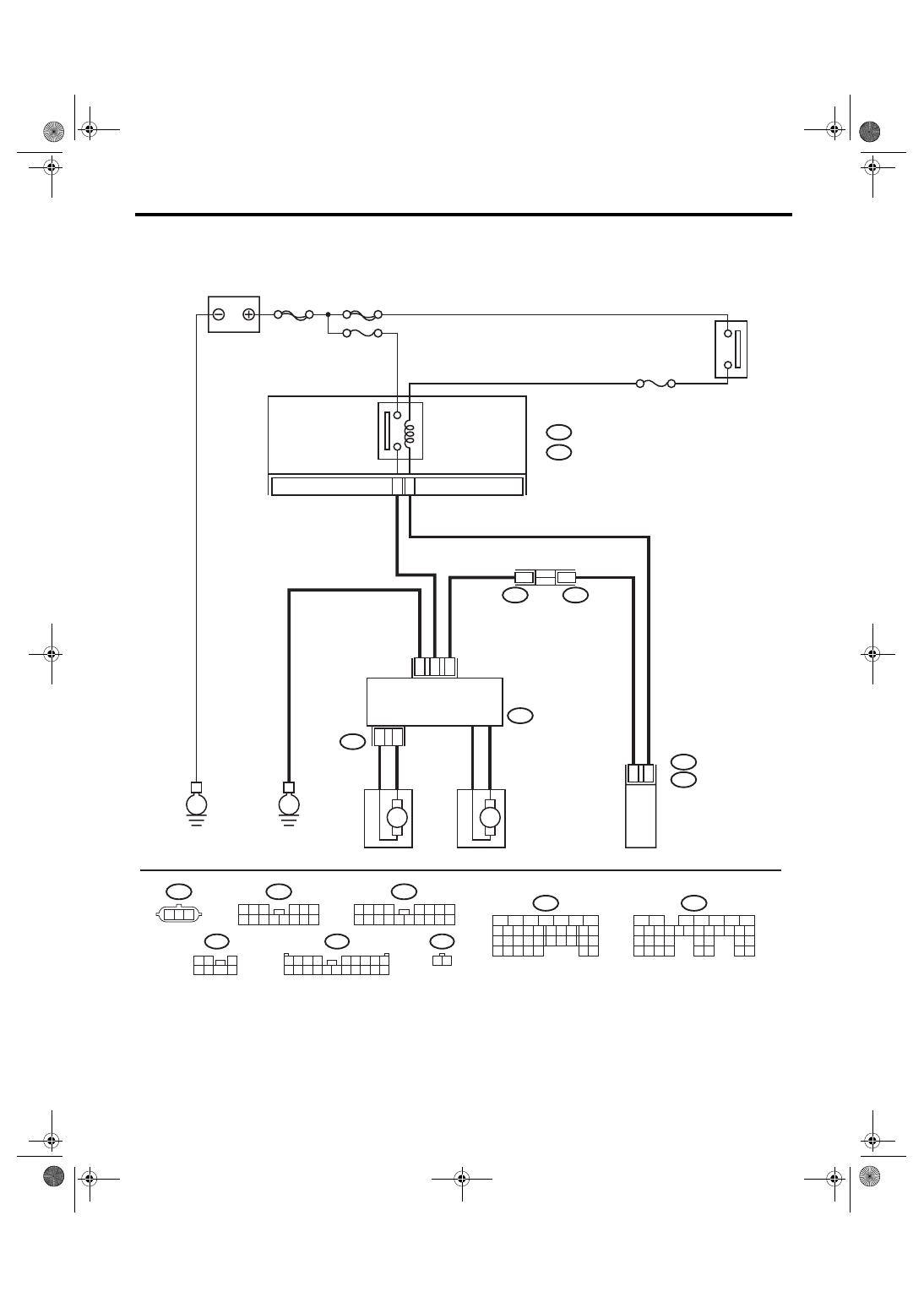
2. Radiator Fan System
A: WIRING DIAGRAM
CO-02163
THROUGH
JOINT CONNECTOR
RADIATOR FAN
CONTROL UNIT
3
1
2
B134
A:
B135
B:
ECM
16
F108
F106
7
B361
SUB FAN MOTOR
A:
1
7
F108
2 3
8
10
1
9
4
11 12 13 14 15 16
5 6 7
17 18
B134
8
5
6
10 11 12 13 14 15
7
2
1
3
4
16
30
19 20
22
28 29
9
17
18
25
21
23 24
32
31
26 27
33 34
B135
5
6
7
2
1
3
4
29
10 11 12 13 14 15
25
24
16
30
9
8
17 18 19
20
28
21 22 23
32
31
26 27
33
34 35
B:
B361
1
7
2 3
4 5 6
8 9 10 11 12 13 14
MAIN FAN MOTOR
B30
A31
F106
1 2 3
B7
E
SBF-6
MAIN SBF
No.2
No.26
B143
B:
F36
E:
IGNITION
SWITCH
MAIN FUSE BOX (M/B)
MAIN
FAN
RELAY 1
E6
3
1 2
7
4 5
6
F36
E:
B143
1 2 3 4
5 6 7
12 13 14 15 16 17 18
B:
8
19
11
9
20
10
E
M
M
F17
1
2
F17
1 2
CO(H6DO)-9
COOLING
Radiator Fan System
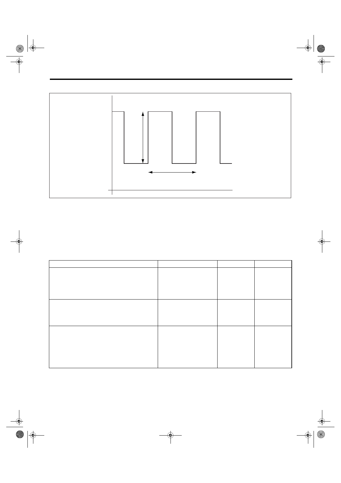
B: RADIATOR FAN CONTROL OUTPUT WAVEFORM
C: INSPECTION
DETECTING CONDITION:
• Engine coolant temperature is more than 93
°C (199°F).
• A/C switch is turned OFF.
• Vehicle speed is below 19 km/h (12 MPH).
TROUBLE SYMPTOMS:
Radiator main fan and sub fan do not rotate under the above conditions.
(A)
5 V
(B)
4 ms
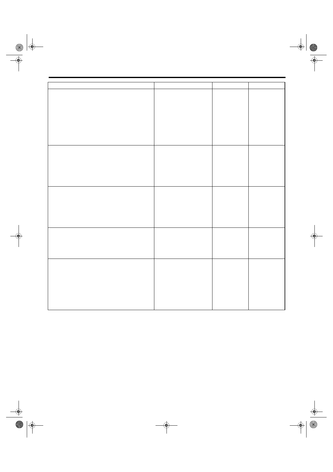
Step
Check
Yes
No
1
CHECK MAIN FAN RELAY 1.
1) Turn the ignition switch to OFF.
2) Remove the main fan relay 1 from main
fuse box.
3) Measure the resistance of terminal in main
fan relay 1 switch.
Is the resistance more than 1
M
Ω?
Replace the main
fan relay 1.
2
CHECK MAIN FAN RELAY 1.
1) Connect the battery to terminal of main fan
relay 1 coil.
2) Measure the resistance between terminals
of main fan relay 1 switch.
Is the resistance less than 1
Ω?
Replace the main
fan relay 1.
3
CHECK POWER SUPPLY FOR ECM.
1) Turn the ignition switch to OFF.
2) Disconnect the connector from ECM.
3) Turn the ignition switch to ON.
4) Measure the voltage between ECM termi-
nal and chassis ground.
Connector & terminal
(B135) No. 30 (+) — Chassis ground (
−
):
Is the voltage more than 10 V? Go to step 4.
Repair the power
supply line.
CO-02139
(V)
0
(A)
(B)
CO(H6DO)-10
COOLING
Radiator Fan System
4
CHECK POWER SUPPLY FOR RADIATOR
FAN CONTROL UNIT.
1) Turn the ignition switch to OFF.
2) Connect the connector to ECM.
3) Disconnect the connector from radiator fan
control unit.
4) Turn the ignition switch to ON.
5) Measure the voltage between radiator fan
control unit terminal and chassis ground.
Connector & terminal
(F106) No. 1 (+) — Chassis ground (
−
):
Is the voltage more than 10 V? Go to step 5.
Repair the power
supply line.
5
CHECK HARNESS BETWEEN ECM AND RA-
DIATOR FAN CONTROL UNIT.
1) Turn the ignition switch to OFF.
2) Disconnect the connector from ECM.
3) Measure the resistance between radiator
fan control unit and ECM connector.
Connector & terminal
(B134) No. 31 — (F106) No. 2:
Is the resistance less than 1
Ω?
Repair the open
circuit in harness
between ECM and
radiator fan con-
trol unit.
6
CHECK RADIATOR FAN CONTROL UNIT
AND GROUND CIRCUIT.
1) Connect the connector to ECM and radiator
fan control unit.
2) Measure the resistance between radiator
fan control unit connector and chassis ground.
Connector & terminal
(F106) No. 3 — Chassis ground:
Is the resistance less than 5
Ω?
Repair the open
circuit in harness
between radiator
fan control unit
connector and
chassis ground.
7
CHECK FAN MOTOR.
1) Disconnect the connector from radiator fan
control unit.
2) Connect the battery positive (+) terminal to
terminal No. 1 of radiator fan control unit, and
the ground (
−) terminal to terminal No. 3.
Does the fan motor rotate?
Replace the fan
motor which does
not rotate.
8
CHECK OUTPUT SIGNAL FROM ECM.
1) Turn the ignition switch to OFF.
2) Connect the test mode connector.
3) Turn the ignition switch to ON.
4) Check the output waveform using oscillo-
scope. <Ref. to CO(H6DO)-9, RADIATOR FAN
CONTROL OUTPUT WAVEFORM, Radiator
Fan System.>
Connector & terminal
(B134) No. 31 (+) — Chassis ground (
−
):
Is waveform being output?
Replace the radia-
tor fan control unit.
<Ref. to
CO(H6DO)-26,
Radiator Fan Con-
trol Unit.>
Replace the ECM.
<Ref. to
FU(H6DO)-34,
Engine Control
Module (ECM).>
Step
Check
Yes
No
Нет комментариевНе стесняйтесь поделиться с нами вашим ценным мнением.
Текст