Subaru Legacy (2005 year). Service manual — part 29
PM-23
PERIODIC MAINTENANCE SERVICES
Engine Coolant
11) Wait for one minute after the engine stops,
open the radiator (for turbo model, coolant filler
tank) cap. If the engine coolant level drops, add en-
gine coolant to the filler neck position of radiator
(for turbo model, coolant filler tank).
12) Perform the procedures 9) and 10) again.
13) Attach the radiator (for turbo model, coolant fill-
er tank) cap and reservoir tank cap properly.
14) Start the engine and operate the heater at max-
imum hot position and the blower speed setting to
“LO”.
15) Run the engine at 2,000 rpm or less until radia-
tor fan starts and stops.
NOTE:
• Be careful with the engine coolant temperature
gauge to prevent overheating.
• If the radiator hose becomes to harden by the
pressure of engine coolant, air bleeding operation
seems to be almost completed.
16) Stop the engine and wait until engine coolant
temperature lowers to 30
°C (86°F) or less.
17) Open the radiator (for turbo model, coolant filler
tank) cap. If the engine coolant level drops, add en-
gine coolant to the filler neck position of radiator
and the “FULL” level of reservoir tank.
18) Attach the radiator (for the turbo model, coolant
filler tank) cap and reservoir tank cap properly.
19) Operate the heater at maximum hot position
and the blower speed setting to “LO” and start the
engine. Race at less than 3,000 rpm. If the flowing
sound is heard, perform the procedures from 15)
again.
2. RERATIONSHIP OF SUBARU COOLANT
CONCENTRATION AND FREEZING TEM-
PERTAURE
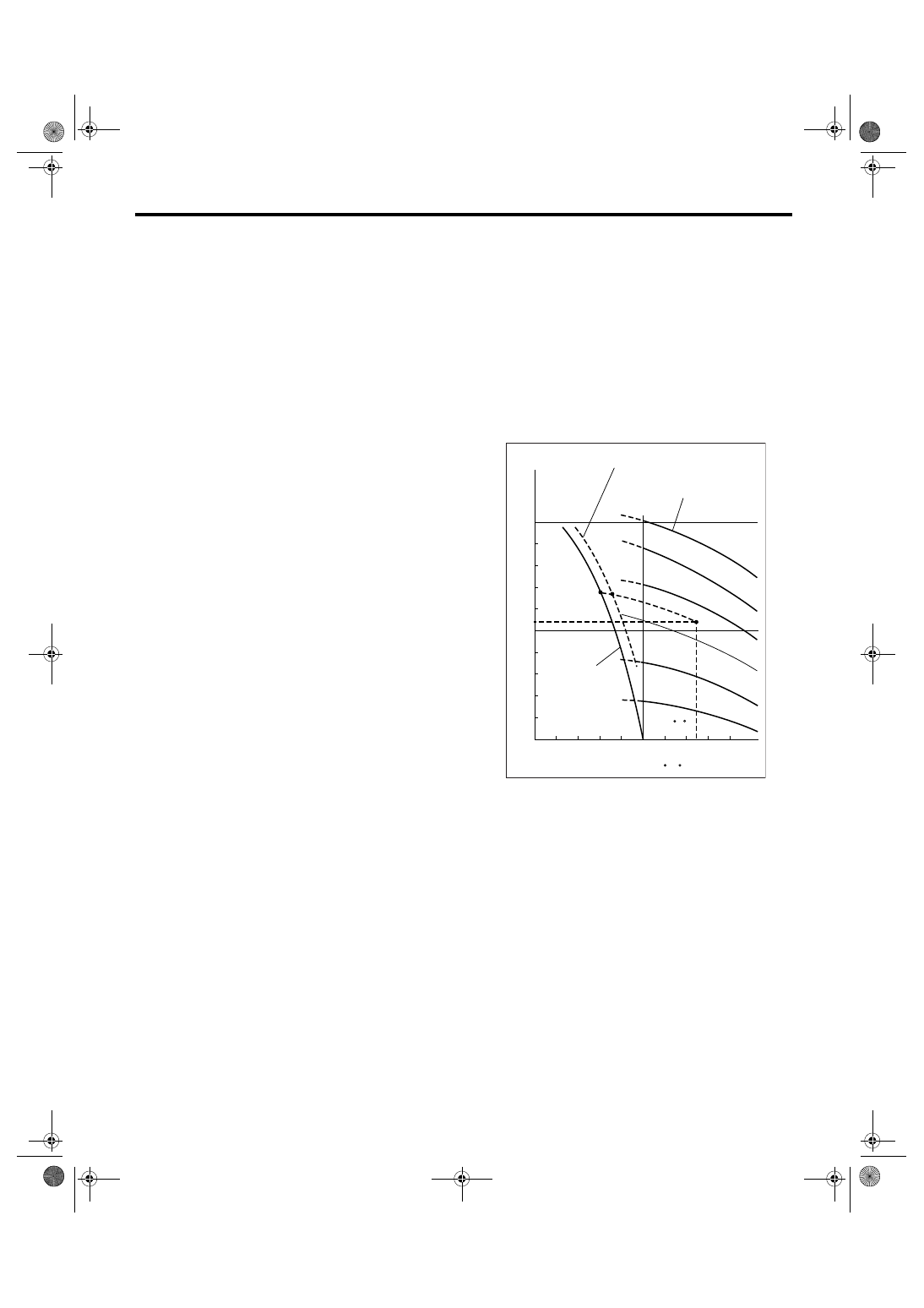
Concentration and safe operating temperature of
SUBARU coolant is shown in the diagram. Measur-
ing the temperature and specific gravity of the cool-
ant will provide this information.
[Example]
If the coolant temperature is 25
°C (77°F), its specif-
ic gravity is 1.054 and the concentration is 35%
(point A), the safe operating temperature is
−14°C
(7
°F) (point B), and the freezing temperature is −
20
°C (−4°F) (point C).
CO-02172
60%
(1.054)
1.000
1.010
1.020
1.030
1.040
1.050
1.060
1.070
1.080
1.090
1.100
Safe operating temperature
Freezing
temperature
Concentration
of coolant
Specific gravity
of coolant
Coolant temperature
B
A
C
-40
(-40) (-22) (-4) (14) (32) (50) (68) (86)
( F)
(104)
-30
-20 -10
0
10
20
30
40
(77 F)
50%
40%
30%
20%
25 C
10%
C
PM-24
PERIODIC MAINTENANCE SERVICES
Engine Coolant
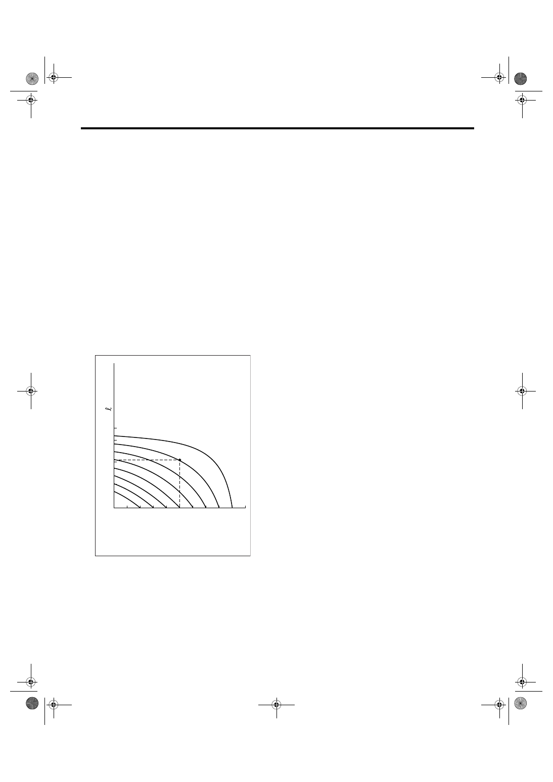
3. PROCEDURE TO ADJUST THE CON-
CENTRATION OF THE COOLANT
To adjust the concentration of coolant according to
temperature, find the proper fluid concentration in
the above diagram and replace the necessary
amount of coolant with an undiluted solution of
SUBARU genuine coolant (concentration 50%).
The amount of coolant that should be replaced can
be determined using the diagram.
[Example]
Assume that the coolant concentration must be in-
creased from 25% to 40%. Find point A, where the
25% line of coolant concentration intersects with
the 40% curve of the necessary coolant concentra-
tion, and read the scale on the vertical axis of the
graph at height A. The quantity of coolant to be
drained is 2.1
2 (2.2 US qt, 1.8 Imp qt). Drain 2.1
2 (2.2 US qt, 1.8 Imp qt) of coolant from the cool-
ing system and add 2.1
2 (2.2 US qt, 1.8 Imp qt) of
the undiluted solution of SUBARU coolant.
If a coolant concentration of 50% is needed, drain
all the coolant and refill with the undiluted solution
only.
CO-00012
10
0
1
2
3
(1.1,
0.9)
(2.1,
1.8)
(3.2,
2.6)
10% 15%
25%
20%
30%
35%
40%
45%
A
20
30
40
50
Concentration of coolant in vehicie
and quantity to be drained
Quantity of coolant to be
drained (US qt, Imp qt)
Necessary Concentration
of coolant
Concentration of coolant in
the vehicie cooling system %
PM-25
PERIODIC MAINTENANCE SERVICES
Clutch System
12.Clutch System
A: INSPECTION AND ADJUSTMENT
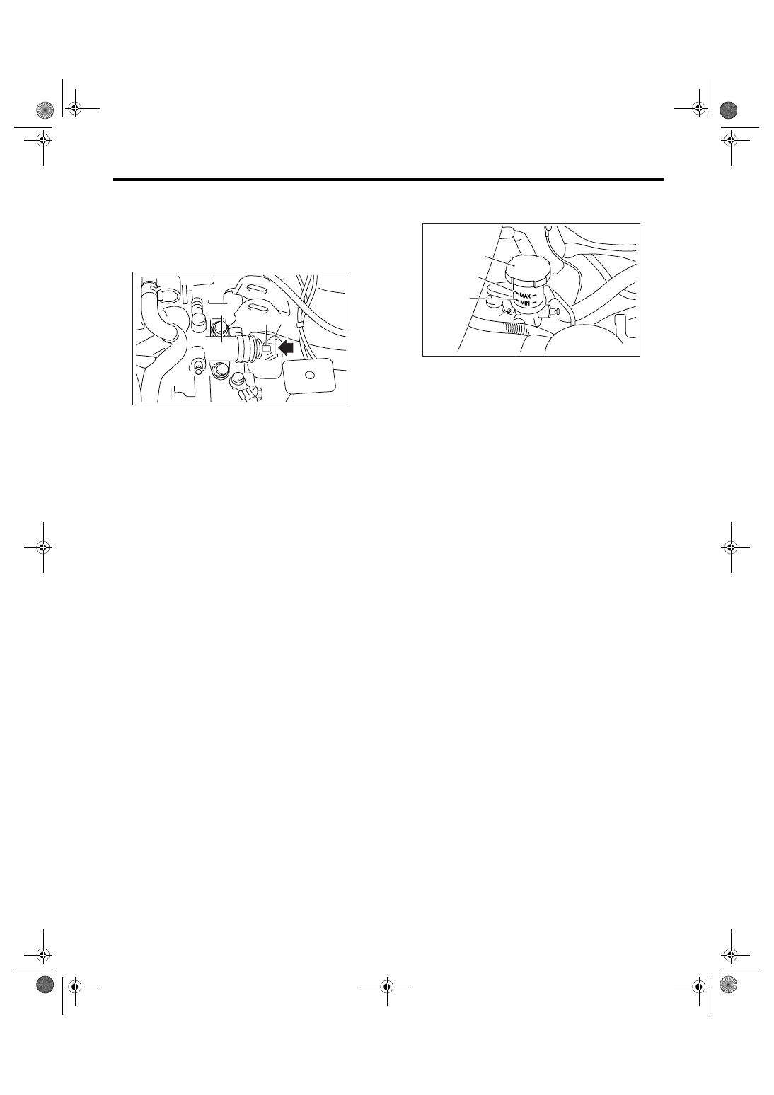
1) Push the release lever to retract the push rod of
the operating cylinder and check if the fluid level in
the clutch reservoir tank rises or not.
2) If the fluid level rises, pedal free play is correct.
3) If the fluid level does not rise, or the push rod
cannot be retracted, adjust the clutch pedal. <Ref.
to CL-36, Clutch Pedal.>
4) Check the fluid level using the scale on the out-
side of the clutch reservoir tank (A). If the level is
below “MIN” (B), inspect the clutch master cylinder,
operating cylinder and hydraulic line for fluid leaks.
If fluid leaks are found, repair or replace. If fluid
leaks are not found, add clutch fluid to bring it up to
“MAX” (C) of clutch reservoir tank.
Recommended clutch fluid:
Refer to “RM” section. <Ref. to RM-5, FLUID,
RECOMMENDED MATERIALS, Recommend-
ed Materials.>
CAUTION:
Prevent the clutch fluid from being splashed
over vehicle body and exhaust pipe. If the
clutch fluid is splashed over vehicle body and
exhaust pipe, flush it quickly, and then wipe it
up.
NOTE:
• Avoid mixing different brands of brake fluid to
prevent degradation of the fluid.
• Be careful not to allow dirt or dust to get into the
reservoir tank.
(A) Release lever
(B) Push rod
(C) Operating cylinder
PM-00164
(C)
(B) (A)
(A) Reservoir tank
(B) MIN. level
(C) MAX. level
(A)
(C)
(B)
PM-00165
PM-26
PERIODIC MAINTENANCE SERVICES
Transmission Gear Oil
13.Transmission Gear Oil
A: REPLACEMENT
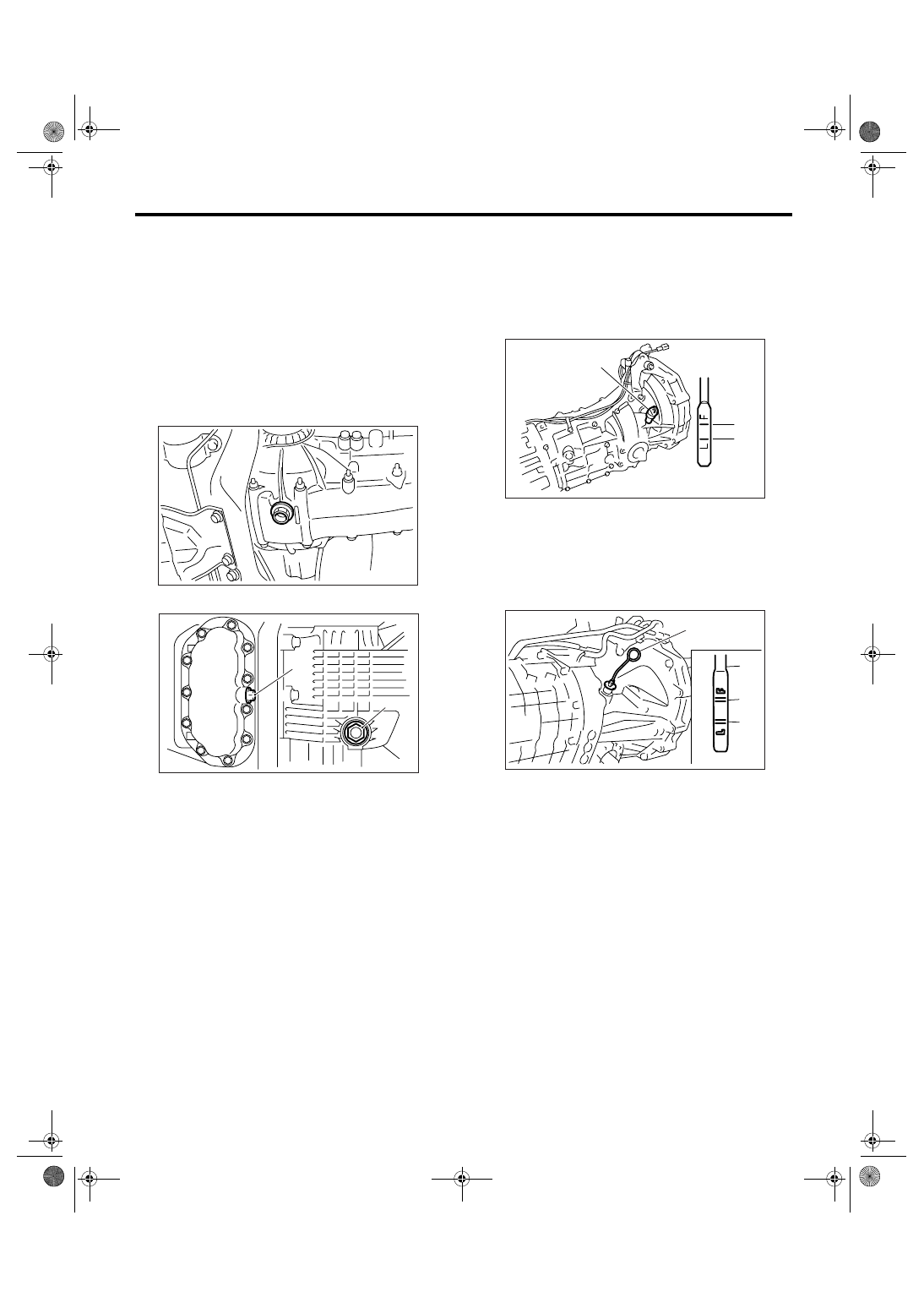
1. MANUAL TRANSMISSION
1) Drain the gear oil by removing drain plug.
NOTE:
• Before starting work, cool off the transmission
gear oil well.
• If transmission gear oil adheres to the exhaust
pipe, wipe it off completely.
• 5MT
• 6MT
2) Replace the gasket with new one, and then tight-
en the drain plug to specified torque.
Tightening torque:
5MT
70 N
⋅
m (7.1 kgf-m, 51.6 ft-lb)
6MT (Oil pan side)
44 N
⋅
m (4.5 kgf-m, 32.5 ft-lb)
6MT (Clutch housing side)
70 N
⋅
m (7.1 kgf-m, 51.6 ft-lb)
3) Fill the transmission gear oil through the oil level
gauge hole up to the upper point of level gauge.
Recommended gear oil:
Refer to “RM” section. <Ref. to RM-3, LUBRI-
CANTS, RECOMMENDED MATERIALS, Rec-
ommended Materials.>
NOTE:
Each oil manufacturer has its base oil and addi-
tives. Thus, do not mix two or more brands.
Gear oil capacity:
5MT
3.5
2 (3.7 US qt, 3.1 Imp qt)
6MT
4.1
2 (4.3 US qt, 3.6 Imp qt)
(A) Drain plug (Oil pan side)
(B) Drain plug (Clutch housing side)
PM-00166
(A)
(B)
MT-00450
(A) Oil level gauge
(B) Upper level
(C) Lower level
(A) Oil level gauge
(B) Upper level
(C) Lower level
PM-00030
(B)
(C)
(A)
MT-00449
(A)
(A)
(B)
(C)
Нет комментариевНе стесняйтесь поделиться с нами вашим ценным мнением.
Текст