Subaru Legacy (2005 year). Service manual — part 415
LU(H6DO)-3
LUBRICATION
General Description
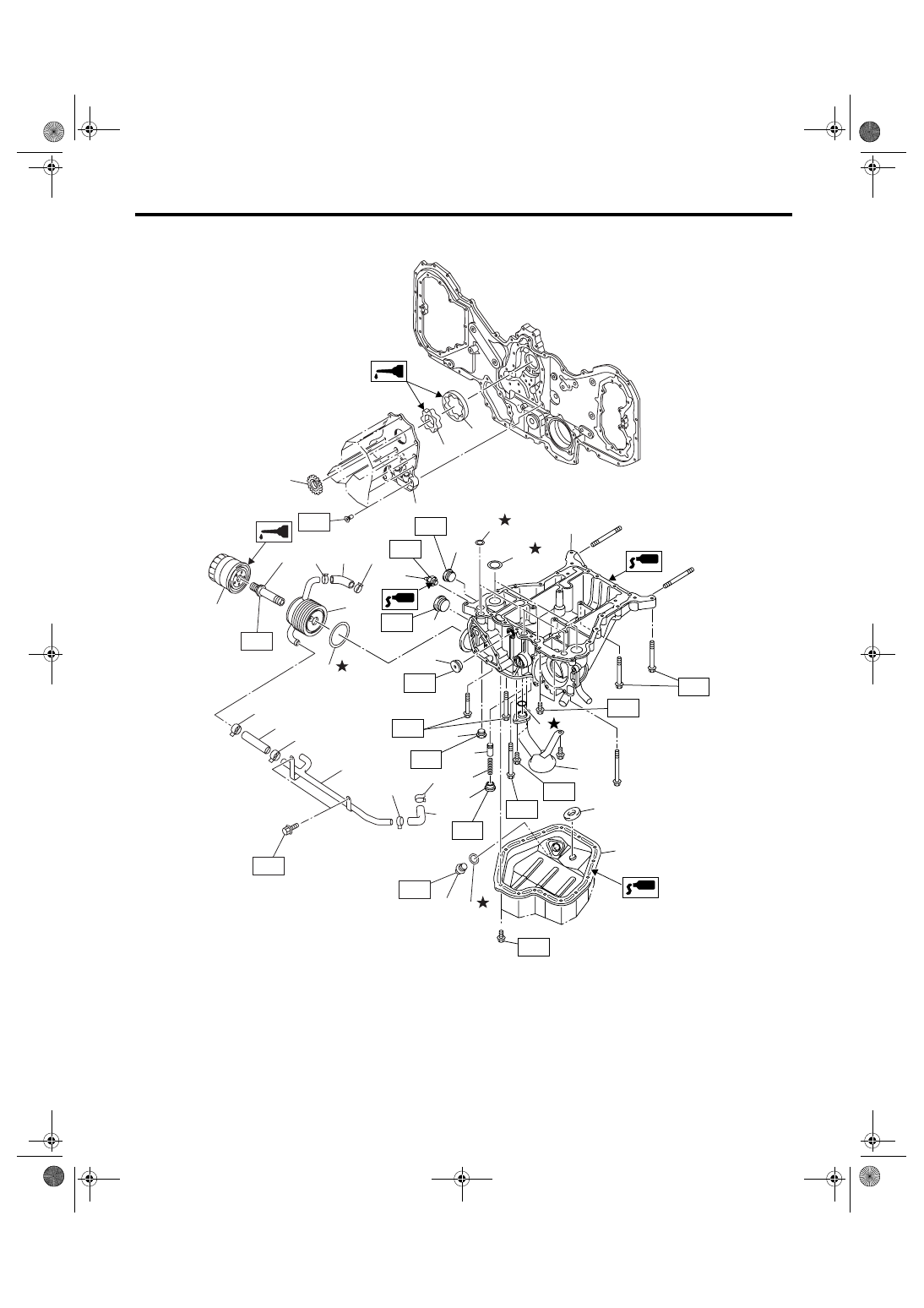
B: COMPONENT
LU-02150
(4)
(3)
T8
(8)
(16)
(20)
(2)
(17)
(13)
(7)
(9)
(6)
(7)
(14)
(18)
(1)
(21)
(19)
(25)
(24)
(23)
T1
T4
T4
T1
T4
T7
T6
T4
T5
T3
T8
T10
(8)
(8)
(11)
(10)
T9
(12)
T2
(15)
(8)
(22)
(6)
(7)
(7)
(7)
(7)
(6)
(5)
T1
LU(H6DO)-4
LUBRICATION
General Description
C: CAUTION
• Wear work clothing, including a cap, protective
goggles and protective shoes during operation.
• Remove contamination including dirt and corro-
sion before removal, installation or disassembly.
• Keep the disassembled parts in order and pro-
tect them from dust and dirt.
• Before removal, installation or disassembly, be
sure to clarify the failure. Avoid unnecessary re-
moval, installation, disassembly and replacement.
• Be careful not to burn yourself, because each
part on the vehicle is hot after running.
• Be sure to tighten fasteners including bolts and
nuts to the specified torque.
• Place shop jacks or rigid racks at the specified
points.
• Before disconnecting connectors of sensors or
units, be sure to disconnect the ground cable from
battery.
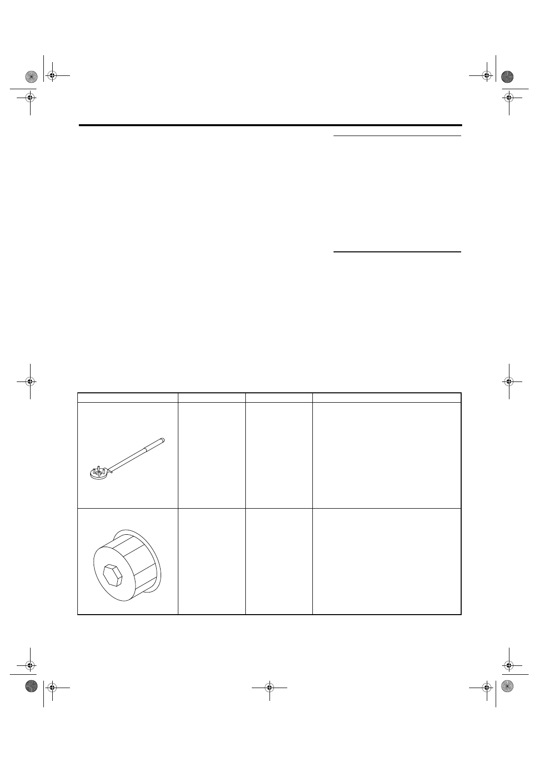
D: PREPARATION TOOL
1. SPECIAL TOOL
(1)
Oil pan lower
(14)
Outer rotor
Tightening torque: N
⋅
m (kgf-m, ft-lb)
(2)
Magnet
(15)
Crank sprocket
T1: 6.4 (0.65, 4.7)
(3)
Drain plug
(16)
Oil pan upper
(4)
Gasket
(17)
Plug
(5)
Oil cooler pipe
(18)
Plug
T3: 16 (1.6, 12)
(6)
Hose
(19)
Plug
T4: 18 (1.8, 13)
(7)
Clamp
(20)
Oil pressure switch
T5: 23 (2.3, 17)
(8)
O-ring
(21)
Plug
T6: 25 (2.5, 18.4)
(9)
Oil cooler
(22)
Oil strainer
T7: 37 (3.8, 27)
(10)
Oil cooler connector
(23)
Plug
T8: 44 (4.5, 32.5)
(11)
Oil filter
(24)
Relief valve spring
T9: 54 (5.5, 40)
(12)
Oil pump cover
(25)
Relief valve
T10: 90 (9.2, 66)
(13)
Inner rotor
ILLUSTRATION
TOOL NUMBER
DESCRIPTION
REMARKS
499977100
CRANK PULLEY
WRENCH
Used for stopping rotation of crank pulley when
removing and tightening crank pulley bolt.
498547000
OIL FILTER
WRENCH
Used for removing and installing oil filter.
ST-499977100
ST-498547000
LU(H6DO)-5
LUBRICATION
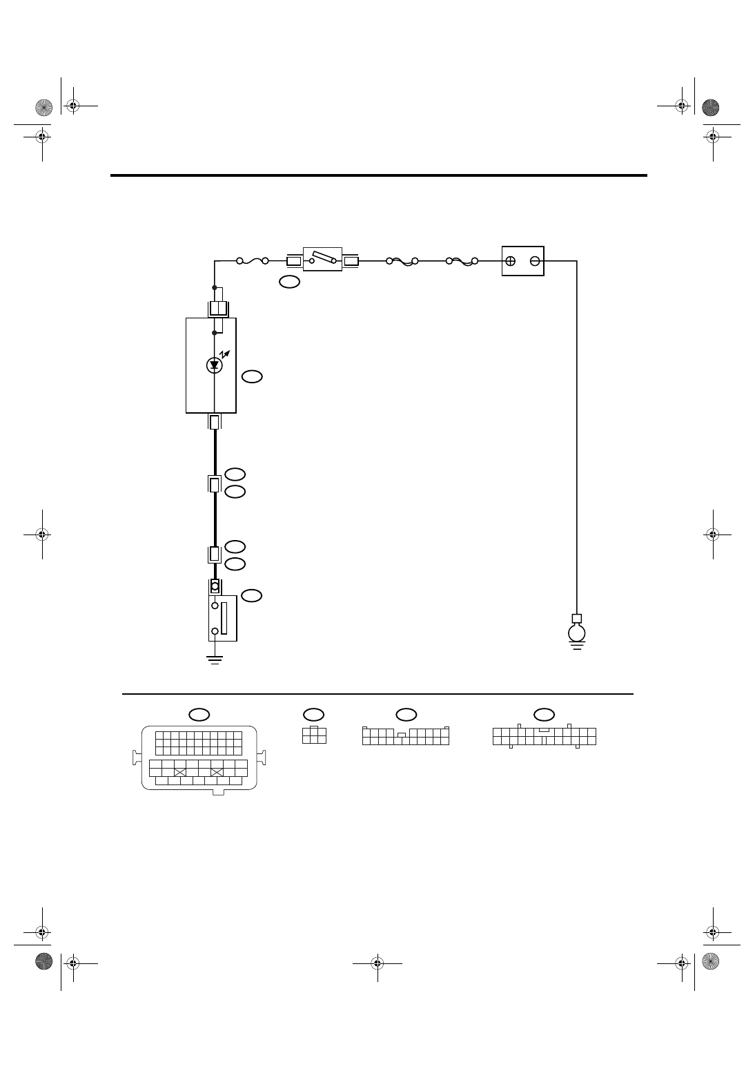
Oil Pressure System
2. Oil Pressure System
A: WIRING DIAGRAM
LU-02155
E
i10
i3
B38
3
15
B21
E2
17
E11
No.5
SBF-6
MAIN SBF
B72
3
6
BATTERY
IGNITION
SWITCH
COMBINATION
METER
OIL PRESSURE
W
ARNING LIGHT
OIL PRESSURE
SWITCH
31
4
B21
1 2 3 4
12 13 14 15
5 6 7 8
16 17 18 19
9 10 11
20 21 22
23 24 25 26 27 28 29 30 31 32 33
35
34
37
36
39
38
41
40
43
42
44
45
47
46
49
48
51
50
53
52
54
1
3
4 5 6
2
B72
1 2 3 4
5 6 7 8 9
10 11 12 13 14 15 16 17 18 19 20
B38
i10
2
1
3 4
6 7 8 9 10
22
21
20
19
18
17
16
15
14
13
12
11
5
LU(H6DO)-6
LUBRICATION
Oil Pressure System
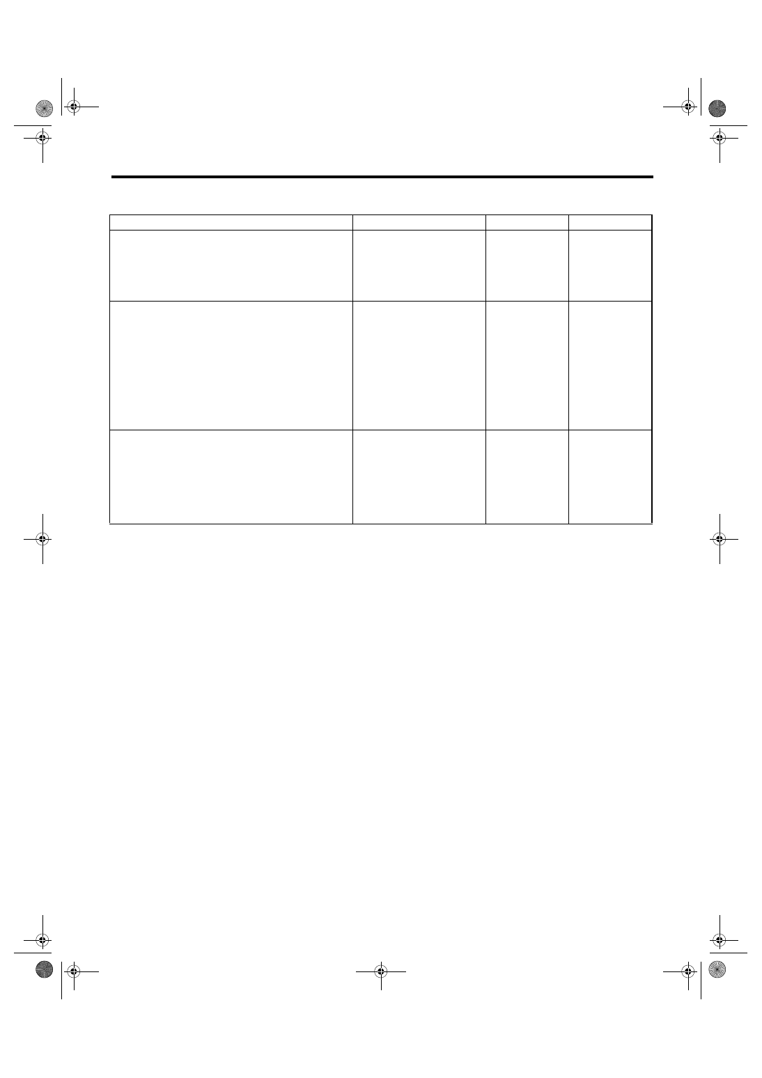
B: INSPECTION
Step
Check
Yes
No
1
CHECK COMBINATION METER.
1) Turn the ignition switch to ON. (Engine
OFF)
2) Check the warning light of combination
meter.
Does the warning light illumi-
nate?
Repair or replace
the combination
meter. <Ref. to IDI-
3, INSPECTION,
Combination
Meter System.>
2
CHECK HARNESS CONNECTOR BETWEEN
COMBINATION METER AND OIL PRES-
SURE SWITCH.
1) Turn the ignition switch to OFF.
2) Disconnect the connector from oil pressure
switch.
3) Turn the ignition switch to ON.
4) Measure the voltage in harness between oil
pressure switch connector and chassis ground.
Connector & terminal
(E11) No. 1 (+) — Chassis ground (
−
):
Is the voltage more than 10 V? Replace the oil
pressure switch.
3
CHECK COMBINATION METER.
1) Turn the ignition switch to OFF.
2) Remove the combination meter.
3) Measure the resistance of combination
meter.
Terminals
(i10) No. 4 — (i10) No. 15:
(i10) No. 3 — (i10) No. 15:
Is the resistance less than 10
Ω?
Replace the har-
ness connector
between combina-
tion meter and oil
pressure switch.
Repair or replace
the combination
meter. <Ref. to IDI-
3, INSPECTION,
Combination
Meter System.>
Нет комментариевНе стесняйтесь поделиться с нами вашим ценным мнением.
Текст